Online publication date 18 Jun 2024
바람-파랑 오정렬과 요 오차가 15 MW급 부유식 해상풍력터빈의 출력 성능과 동적 응답에 미치는 영향
Copyright © 2024 by the New & Renewable Energy
This is an Open Access article distributed under the terms of the Creative Commons Attribution Non-Commercial License (http://creativecommons.org/licenses/by-nc/3.0) which permits unrestricted non-commercial use, distribution, and reproduction in any medium, provided the original work is properly cited.
Abstract
Floating offshore wind turbines (FOWTs) have been developed to overcome large water depths and leverage the abundant wind resource in deep seas. However, wind-wave misalignment can occur depending on the weather conditions, and most megawatt (MW)-class turbines are horizontal-axis wind turbines subjected to yaw errors. Therefore, the power performance and dynamic response of super-large FOWTs exposed simultaneously to these external conditions must be analyzed. In this study, several scenarios combining wind-wave misalignment and yaw error were considered. The IEA 15 MW reference FOWT (v1.1.2) and OpenFAST (v3.4.1) were used to perform numerical simulations. The results show that the power performance was affected more significantly by the yaw error; therefore, the generator power reduction and variability increased significantly. However, the dynamic response was affected more significantly by the wind-wave misalignment increased; thus, the change in the platform 6-DOF and tower loads (top and base) increased significantly. These results can be facilitate improvements to the power performance and structural integrity of FOWTs during the design process.
Keywords:
Floating offshore wind turbine, Design load case, Wind-wave misalignment, Yaw error, Degrees of freedom키워드:
부유식 해상풍력터빈, 설계 하중 조건, 바람-파랑 오정렬, 요 오차, 자유도1. 서 론
글로벌 해상풍력 자원 잠재량의 약 80%가 수심 60 m 이상의 먼바다에 존재하는 것으로 추정되는데,[1] 높은 풍력 에너지 밀도와 낮은 난류 강도를 보이는 원해의 바람 자원은 이용률(Capacity Factor)과 가동률(Availability) 측면에서 유리한 특징을 보인다. 깊은 수심 지역에서 더 많은 발전량을 얻기 위해 부유식 풍력발전시스템이 개발・실증 중이며, 본격적인 대규모 부유식 풍력발전단지 상용화를 앞두고 있다. 풍력터빈-부유체(Floater)-계류시스템(Mooring System)으로 구성된 부유식 풍력발전시스템은 고정식보다 운동 제어 및 자세 유지가 어려운 특징을 보인다.[2]
부유식 풍력발전시스템에는 바람, 파랑, 해류의 개별 또는 결합 하중(Combined Load)이 작용하는데, 풍향과 파향의 불일치 조건이 바람-파랑 오정렬(Wind-Wave Misalignment)이다. 이는 주로 대기 안정도가 안정적이거나 낮은 평균 풍속 조건에서 발생 빈도가 증가하는 것으로 알려져 있다.[3,4] 바람-파랑 오정렬은 외부 환경조건 영향을 크게 받는 부유식 풍력발전시스템의 하중과 발전량 변화를 유발할 수 있다.
Barj et al.(2014)은 부유식 풍력발전시스템이 바람-파랑 오정렬 상황에 노출될 때, 타워 기저부의 좌우 방향 하중(Side-to-Side, Mx)이 3배 증가할 수 있음을 보였다.[5] 특히, 수평축 풍력터빈은 실시간 풍향 변화를 빠르게 추적하기 어려워 요 오차(Yaw Error) 발생 가능성이 높은 편이다.[6] Li et al.(2020)은 요 오차로 인해 5 MW급 부유식 풍력발전시스템 출력이 최대 7.86% 감소한다는 연구 결과를 발표했다.[7]
바람-파랑 오정렬과 요 오차는 사이트 특성(Site-Specific)에 따라 다양한 조합으로 발생한다. 부유식 풍력발전시스템은 부력과 계류 장치를 이용해 자세를 유지하므로, 이러한 비정상적 외부 환경조건은 출력과 하중에 부정적인 영향을 미치게 된다. 따라서, 특정 설치 환경에서 최적의 성능을 안정적으로 유지하기 위해서는 바람-파랑 오정렬과 요 오차 영향을 설계 하중 조건(Design Load Case, DLC)으로 고려해야 한다. 국제전기기술위원회(IEC)는 풍력터빈의 설계 하중 등 평가 과정에서 이러한 영향을 고려하도록 규정하고 있으며,[8,9] 이들이 부유식 풍력발전시스템의 출력 성능과 하중 변화에 미치는 영향에 관한 일부 연구가 수행된 바 있다. Wang et al.(2022)은 바람-파랑 오정렬 조건에서 부유식 풍력발전시스템의 6-자유도 운동 변화를 분석했고,[10] Yin et al.(2017)은 허리케인 등 극한 환경조건에서의 오정렬이 블레이드와 요 베어링 하중에 미치는 영향을 분석했다.[11] Aju et al.(2023)은 풍동 실험을 통해 전방 풍력터빈의 요 오차가 후방 풍력터빈의 출력 성능과 공기역학적 하중에 미치는 영향을 분석했다.[12]
바람-파랑 오정렬과 요 오차는 결합 하중의 형태로 동시 작용할 가능성이 높은데, 위 연구들은 이들 변수를 상호 독립적으로 적용했기 때문에 운전 중인 부유식 풍력발전시스템의 출력 및 하중 변화를 실제 환경과 같이 모사했다고 보기 어렵다. 따라서, 본 연구에서는 다수의 설계 하중 조건 조합을 통해 이들 변수의 결합 하중이 작용하는 환경을 모사하고, 운전 중인 부유식 풍력발전시스템의 출력, 플랫폼 6-자유도 운동, 타워 하중(상부 및 기저부) 변화를 정량적으로 분석하고자 한다.
2. 부유식 풍력발전시스템
본 연구에서 사용한 부유식 풍력발전시스템은 국제에너지기구(International Energy Agency, IEA) Wind Task 37이 공개한 15 MW급 풍력터빈에 VolturnUS 반잠수식 플랫폼(University of Maine)을 결합한 형태이다. 시스템 모델링과 통합 하중 해석에 OpenFAST(v3.4.1)를 이용했고, Table 1과 2에 주요 제원을 나타냈다.[13,14] 본격적인 해석에 앞서 시스템 모델링 적정성 확인을 위해 동적 거동과 출력 성능을 검증했다. 미국 국립재생에너지연구소(National Renewable Energy Laboratory, NREL)의 ROSCO(Reference Open-Source Controller, v2.7.0) 제어기를 적용한 자유 감쇠 운동(Rigid-Body Free Decays)과 정상 상태 해석(Steady-State Analysis)을 수행했고 IEA Wind Task 37의 연구 결과와 비교하였다.
Table 3은 자유 감쇠 운동의 비교 결과이다. 대부분의 동적 거동 특성이 서로 잘 일치하는 결과를 보여 시스템 모델링이 잘 수행된 것으로 판단된다. 다만, 상하동요(Heave), 종동요(Pitch), 횡동요(Roll) 값이 최대 0.002 Hz의 무시할 만한 수준의 차이를 보이는데, 이는 IEA Wind Task 37에서 사용한 OpenFAST와 버전이 다르고, 참고문헌에서 고유 진동수 해석 조건이 자세히 설명되지 않아 발생한 일부 설정값의 근소한 차이 때문으로 판단된다.
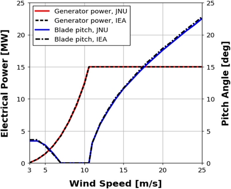
Fig. 1은 정상 상태 해석의 비교 결과이다. 풍속 3 m/s ~ 6.98 m/s 구간에서는 블레이드 3P 회전 주파수가 타워의 고유 진동수에 간섭하는 것을 방지하기 위해 피치 제어가 적용된 것을 확인할 수 있다. 토크제어와 출력제어가 개입하는 시동풍속부터 종단풍속까지 전 구간에서의 출력과 블레이드 피치(Pitch) 각 변화를 IEA Wind Task 37의 연구 결과와 비교했으며 두 결과는 서로 잘 일치한다. 따라서, 본 연구에 사용된 15 MW 부유식 풍력발전시스템 모델링은 적합하게 수행된 것으로 판단된다.
3. 해석 조건 및 시나리오
3.1 설계 하중 조건
IEC 61400-3-1과 3-2는 부유식 풍력발전시스템이 설계수명 동안 경험할 수 있는 상황을 DLC로 정의한다.[9,15] 본 연구는 요 오차와 바람-파랑 오정렬이 결합한 형태로 동시 작용하는 조건에서, 정상 발전 중인 부유식 풍력발전시스템의 출력과 동적 응답 특성 변화를 분석하기 위해 DLC 1.1을 적용했다(Table 4 참조).
DLC 1.1의 확장 시나리오는 정상 난류 모델(Normal Turbulence Model, NTM), 정상 해상 상태(Normal Sea State, NSS), 그리고 요 정렬 불량과 제어 시스템의 추적 오차 등으로 발생할 수 있는 풍향 및 로터 축의 편차를 고려해야 한다. 또한, 방향성 변수로 바람과 파랑이 일치하는 동일 방향(Co-Directional, COD)과 극한 하중을 초래하는 단일 방향(Uni-Directional, UNI) 조건을 적용해야 한다. 그러나 IEC 표준에서는 바람과 파랑의 정렬 불량(Misaligned, MIS)이 부유식 풍력발전시스템에 더 큰 하중을 유발할 경우, 동일 방향을 적용하는 DLC도 정렬 불량 조건을 고려하도록 규정하고 있다. 따라서, 본 연구에서는 COD 대신 MIS를 적용해 작용 하중 측면에서 더 보수적인 상황으로 가정했다.
3.2 해양 환경 조건
본 연구는 Table 5와 같이 미국 동부 해안의 해양 환경 조건을 적용했다. 해양 기상(Metocean)자료는 미국 해양대기청(National Oceanic and Atmospheric Administration, NOAA)이 공개한 실측자료를 후처리한 Stewart et al.(2016)의 연구를 참조했다.[16] 풍속은 정격풍속인 10.59 m/s를 사용했으며, 난류 강도는 0.14를 적용했다. 파랑 스펙트럼은 JONSWAP 스펙트럼을 사용했고, 정격풍속 조건에서의 유의 파고는 1.641 m, 파주기는 7.544 s를 적용했다. 해류 속도는 멕시코 만류의 평균 속도인 1.78 m/s이다.
3.3 시나리오 구성과 좌표계
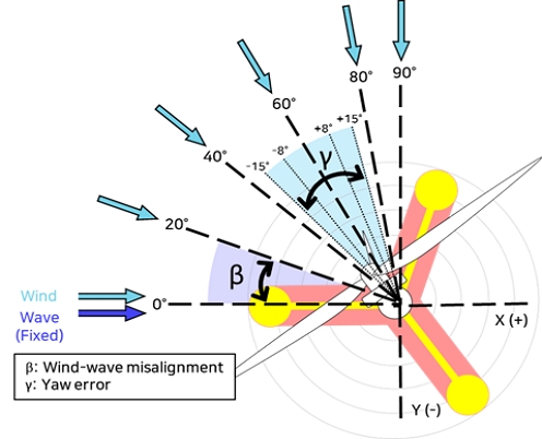
Fig. 2는 바람-파랑 오정렬과 요 오차의 해석 조건 및 좌표계 정의를 나타낸다. 외부 환경조건 변화에 따른 출력 성능과 동적 특성 변화 분석을 위해 DLC 1.1을 기반으로 총 30가지의 확장 시나리오를 구성했다. 바람-파랑 오정렬(β)은 6종류(0°, 20°, 40°, 60°, 80°, 90°), 요 오차(γ)는 5종류(-15°, -8°, 0°, 8°, 15°)로 세분했다. OpenFAST는 타워 중심선과 평균 해수면(Mean Sea Level, MSL) 교차점을 원점으로 정의한다. 따라서, 바람-파랑 오정렬이 증가하거나 요 오차가 음에서 양의 방향으로 변할수록 풍향과 나셀(Nacelle) 축은 y축에 근접하게 된다. 이때 파랑과 조류의 방향은 모든 시나리오에서 0°로 고정했다.
3.4 시나리오별 시계열 데이터 계산
시나리오별 해석시간은 4,000 s이며, 과도응답(Transient Response)을 제거하기 위해 해석 초기 400 s 결과는 제외되었다. 출력 성능 분석을 위해 발전기 측 출력변화 시계열 데이터의 평균값과 표준편차를 구했고, 동적 응답 특성은 반잠수식 플랫폼의 6-자유도 운동과 타워 상부 및 기저부 하중의 변화를 통해 분석되었다.
4. 결과 및 고찰
4.1 발전기 출력 변동성
Fig. 3은 시나리오별 발전기 측 평균 출력 비교 결과를 나타낸다. 바람-파랑 오정렬과 요 오차가 0°인 조건에 비해 대부분 출력이 감소했는데, 바람-파랑 오정렬 0°, 요 오차 -15°일 때 5.3%의 가장 큰 출력 감소율이 나타났다. 요 오차가 0°, 바람-파랑 오정렬이 20°조건에서 출력이 0.03%로 미소하게 증가하는 현상을 보였는데, 물리적으로 유의미한 영향이라 보기 어렵다. 그러므로 동일한 오차 조건에서 바람-파랑 오정렬이 출력 변화에 미치는 영향은 크지 않은 것으로 판단된다.
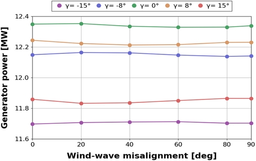
Comparison of mean for generator power between scenarios based on the effect of yaw error and wind-wave misalignment
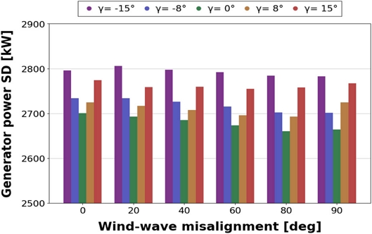
Fig. 4는 발전기 출력의 표준편차 비교 결과이다. 전술한 바와 같이, 동일 바람-파랑 오정렬 조건에서 요 오차가 커질수록 표준편차가 증가하고 있다. 이러한 조건에서 출력 성능은 최대 4.7%의 차이를 보여, 요 오차의 영향을 더 많이 받는 것으로 나타났다. 따라서, 바람-파랑 오정렬과 요 오차의 동시 발생은 출력 감소의 원인이 되며, 요 오차의 영향이 더 크게 작용한다.
4.2 반잠수식 플랫폼의 6-자유도 운동 특성
Fig. 5에 전후동요(Surge), 좌우동요(Sway), 상하동요(Heave)의 시나리오별 제곱평균제곱근(Root Mean Square, RMS) 변화를 나타냈다. Fig. 5(a)에서 바람-파랑 오정렬이 증가하거나, 요 오차가 음에서 양의 방향으로 변화할수록 Surge는 감소하고 Sway는 증가하는 추세를 보이는데, 이는 풍하중(Wind Load)과 추력(Thrust Force)이 시계 방향으로 증가하기 때문이다.
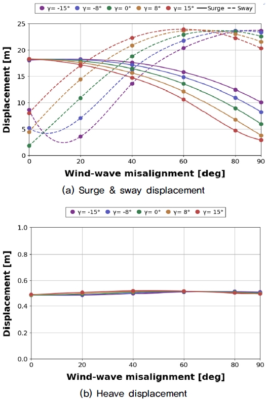
Comparison of RMS for semi-submersible platform translational motion between scenarios based on the effect of yaw error and wind-wave misalignment: (a) surge&sway displacement and (b) heave displacement
바람-파랑 오정렬이 일정하고, 요 오차가 증가하는 조건에서 Surge와 Sway는 각각 17.7%, 55.5%의 변화율을 보였다. 반면에 요 오차가 일정하고, 바람-파랑 오정렬이 증가하는 조건에서는 각각 31.5%와 372.5%의 큰 변화율을 보여, Surge와 Sway 운동 변화는 바람-파랑 오정렬의 영향을 더 크게 받는다. 다만, Fig. 5(b)와 같이 Heave는 다른 병진운동에 비해 바람-파랑 오정렬과 요 오차의 영향을 거의 받지 않는 것으로 나타났다.
Fig. 6은 횡동요(Roll), 종동요(Pitch), 선수동요(Yaw)의 시나리오별 RMS 변화를 나타낸다. Fig. 6(a)와 같이, 바람-파랑 오정렬이 증가하거나 요 오차가 음에서 양의 방향으로 변화할수록 Pitch는 감소하고 Roll이 증가하는 추세를 보인다. 이는 Fig. 5(a)의 Surge와 Sway와 같이 풍하중과 추력이 시계 방향으로 증가하기 때문에 나타나는 현상이다.
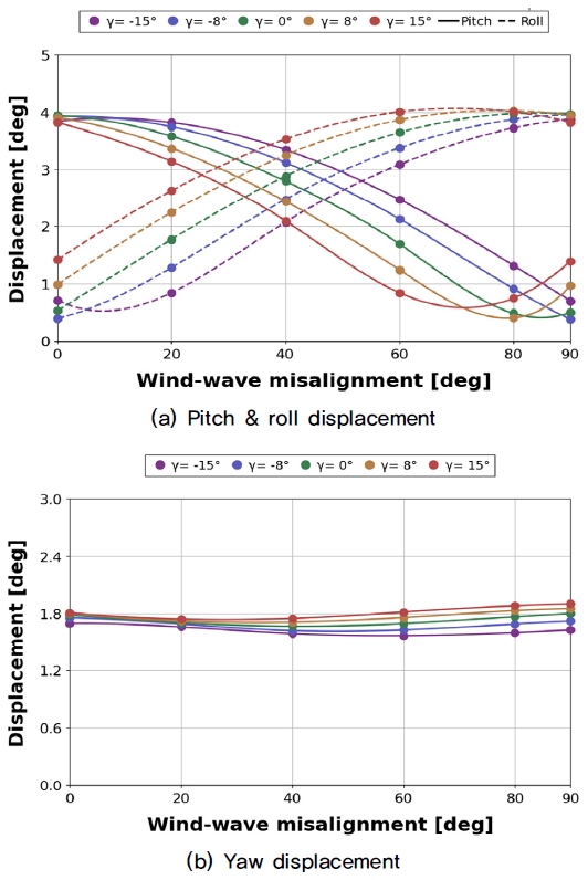
Comparison of RMS for semi-submersible platform rotational motion between scenarios based on the effect of yaw error and wind-wave misalignment: (a) pitch&roll displacement and (b) yaw displacement
바람-파랑 오정렬이 일정한 조건에서 요 오차가 증가할 때, Pitch와 Roll 운동은 각각 38.3%와 25.0%의 변화율을 보였다. 반대로 요 오차가 일정한 조건에서 바람-파랑 오정렬이 증가하는 경우, 51.0%와 372.7%의 변화율을 보여 회전 운동도 마찬가지로 바람-파랑 오정렬의 영향을 더 크게 받는 것으로 나타났다. 다만, Fig. 6(b)와 같이 Yaw 운동 변화율은 모든 조건에서 상대적으로 작게 나타나, 다른 회전 운동에 비해 바람-파랑 오정렬과 요 오차 영향을 크게 받지 않는 것으로 판단된다.
4.3 타워 상부 및 기저부 하중 변동성
Fig. 7은 시나리오별 타워 상부 하중의 RMS 변화를 나타내는데, Fig. 7(a)와 (b)는 좌우 방향(Side-to-Side, Mx)과 전후 방향(Fore-Aft, My) 작용 하중이다. 바람-파랑 오정렬이 증가하거나 요 오차가 음에서 양의 방향으로 변화할수록 Mx는 증가하고 My는 감소하는 추세를 보였다. 바람-파랑 오정렬이 90°, 요 오차가 15°인 조건에서 타워 상부의 Mx 방향 하중은 최대 173.4% 증가했고, My 방향 하중은 최대 87.4% 감소했다. 바람-파랑 오정렬이 일정한 조건에서 요 오차가 증가할 때, Mx 및 My 방향 하중은 각각 49.1%와 20.0%의 변화율 보였다. 반면, 요 오차가 일정한 조건에서 바람-파랑 오정렬이 증가할 때는 각각 177.2%와 29.3%의 변화율을 보여, 타워 상부 하중은 바람-파랑 오정렬의 영향을 더 크게 받는 것으로 판단된다.
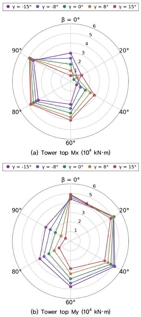
Comparison of RMS for tower top bending moment between scenarios based on the effect of yaw error and wind-wave misalignment: (a) tower top Mx and (b) tower top My
Fig. 8은 시나리오별 타워 기저부에 작용하는 하중의 RMS 변화를 나타내며, Fig. 8(a)와 (b)는 각각 Mx와 My 방향 하중을 의미한다. 타워 기저부도 마찬가지로, 바람-파랑 오정렬이 증가하거나 요 오차가 음에서 양의 방향으로 변화할수록 Mx 방향 하중은 증가하고, My 방향 하중은 감소하는 경향을 보였다. Mx 방향 하중은 바람-파랑 오정렬이 80°, 요 오차가 8°인 조건에서 최대 701.6% 증가했고, My 방향 하중은 바람-파랑 오정렬이 90°, 요 오차가 -8°일 때 최대 90.8% 감소했다. 바람-파랑 오정렬이 일정한 조건에서 요 오차가 증가할 때, Mx 및 My 방향 하중은 평균적으로 각각 26.6%, 39.0% 변화했다. 반대로 요 오차가 일정하고 바람-파랑 오정렬이 증가하는 조건에서는 평균적으로 각각 442.6%, 51.5%의 변화율을 보였다.
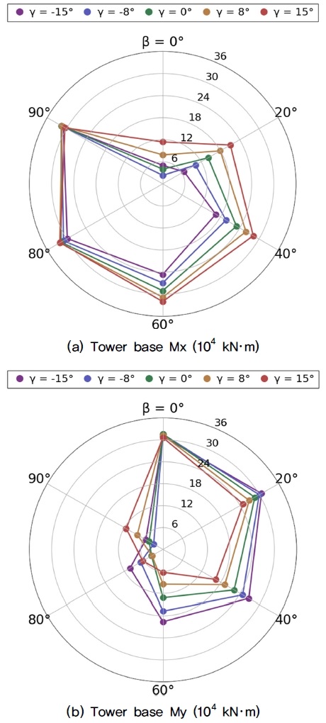
Comparison of RMS for tower base bending moment between scenarios based on the effect of yaw error and wind-wave misalignment: (a) tower base Mx and (b) tower base My
따라서, 타워 기저부 하중도 요 오차보다는 바람-파랑 오정렬의 영향을 더 많이 받는 것으로 판단된다.
5. 결 론
본 연구는 정상 발전 중인 15 MW급 부유식 풍력터빈을 대상으로 바람-파랑 오정렬과 요 오차가 동시에 작용하는 30개의 DLC를 구성해, 시나리오별 터빈 출력, 플랫폼 6-자유도 운동 및 타워에 작용하는 하중 변화율을 정량적으로 분석했다.
부유식 풍력발전시스템의 출력 변화율에는 요 오차가 지배적인 영향을 미쳤는데, 대부분 요 오차가 증가할수록 출력이 감소하는 추세를 보였다. 바람-파랑 오정렬이 0°이고 요 오차가 -15°인 조건에서 최대 5.3%의 출력 감소가 일어났다. 플랫폼 6-자유도 운동은 요 오차보다 바람-파랑 오정렬 영향을 더 크게 받는데, 바람-파랑 오정렬이 증가할수록 Surge와 Pitch 변화율은 감소하고 Sway와 Roll은 증가하는 추세를 보였다. 이들 조건이 Heave와 Yaw 운동 변화에 미치는 영향은 거의 나타나지 않았다. 타워 상부와 기저부에 작용하는 하중 변화율에는 바람-파랑 오정렬이 지배적인 영향을 미쳤는데, 오정렬이 증가할수록 Mx 방향 하중은 증가하고 My 방향 하중은 감소하는 경향을 보였다.
반잠수식 플랫폼을 사용한 부유식 풍력발전시스템은 출력 변동성 측면에서 바람-파랑 오정렬 영향을 거의 받지 않는 것으로 보이므로, 정상 해상 상태에서 출력 성능만을 보고자 할 때는 바람-파랑 오정렬 조건은 고려하지 않아도 될 것으로 판단된다. 반면, 플랫폼의 동적 응답과 극한 하중 해석을 위해서는 바람-파랑 오정렬과 요 오차를 동시에 고려할 필요가 있다.
본 연구의 결과는 정격풍속 조건만을 고려하였으므로 추후 연구에서는 정격풍속 미만 구간과 정격풍속 초과 구간을 고려한 연구를 수행할 예정이다.
Nomenclature
| HS : | significant wave height, m |
| TP : | peak spectral period, s |
| β : | wind-wave misalignment, ° |
| γ : | yaw error, ° |
Subscript
| DOF : | degrees of freedom |
| DLC : | design load case |
| NTM : | normal turbulence model |
| NSS : | normal sea state |
| MIS : | misaligned |
| RMS : | root mean square |
Acknowledgments
이 논문은 2024학년도 제주대학교 교원성과지원사업에 의하여 연구되었음.
References
- Global Wind Energy Council (GWEC), 2022, “Floating offshore wind —A global opportunity”, GWEC, https://gwec.net/wp-content/uploads/2022/03/GWEC-Report-Floating-Offshore-Wind-A-Global-Opportunity.pdf, .
-
Clement, C., Kosleck, S., and Lie, T., 2021, “Investigation of viscous damping effect on the coupled dynamic response of a hybrid floating platform concept for offshore wind turbines”, Ocean Engineering, 225, 108836.
[https://doi.org/10.1016/j.oceaneng.2021.108836]

- Barth, S., and Eecen P.J., 2008, “Description of the relation of wind, wave and current characteristics at the offshore wind farm egmond aan zee(OWEZ) location in 2006”, Energy research Center of the Netherlands, https://www.shell.nl/about-us/what-we-do/wind/rapporten/_jcr_content/root/main/section/revealer_copy_1609704471/revealer_item_1822097627.multi.stream/1701448769678/6644ea7222c5ef512129c07e06a589afd4becb18/owez-r-122-wave-characteristics.pdf, .
-
Van Vledder, G.P., 2013, “On wind-wave misalignment, directional spreading and wave loads”, Proc. The 32nd International Conference on Offshore Mechanics and Arctic Engineering, V005T06A087.
[https://doi.org/10.1115/OMAE2013-11393]

-
Barj, L., Jonkman, J.M., Robertson, A., Stewart, G.M., Lackner, M.A., Haid, L., Matha, D., and Stewart, S.W., 2014, “Wind/wave misalignment in the loads analysis of a floating offshore wind turbine”, Proc. The 32nd American Society of Mechanical Engineers Wind Energy Symposium, 0363.
[https://doi.org/10.2514/6.2014-0363]

-
Salic, T., Charpentier, J.F., Benbouzid, M., and Le Boulluec, M., 2019, “Control strategies for floating offshore wind turbine: Challenges and trends”, Electronics, 8(10), 1185.
[https://doi.org/10.3390/electronics8101185]

-
Li, X., Zhu, C., Fan, Z., Chen, X., and Tan, J., 2020, “Effects of the yaw error and the wind-wave misalignment on the dynamic characteristics of the floating offshore wind turbine”, Ocean Engineering, 199, 106960.
[https://doi.org/10.1016/j.oceaneng.2020.106960]

- International Electrotechnical Commission (IEC), 2019, “Wind energy generation systems - Part 1: design requirements”, IEC 61400-1 Standard, 4th Edition, Geneva (Switzerland).
- International Electrotechnical Commission (IEC), 2019, “Wind energy generation systems - Part 3-1: design requirements for fixed offshore wind turbines”, IEC 61400-3-1 Standard, 1st Edition, Geneva (Switzerland).
-
Wang, B., Li, Y., Gao, S., Shen, K., Hu, Z., and Zheng, X., 2022, “Motion characteristics and aero-elastic responses of floating offshore wind turbine under coupling action of waves and winds”, Front. Environ. Sci., 10, 965334.
[https://doi.org/10.3389/fenvs.2022.965334]

-
Yin, L.L., Lo, K.H., and Wang, S.S., 2017, “Effects of blade pitch, rotor yaw, and wind-wave misalignment on a large offshore wind turbine dynamics in western gulf of mexico shallow water in 100-year return hurricane”, J. Offshore Mech. Arct. Eng., 139(1), 011901.
[https://doi.org/10.1115/1.4034330]

-
Aju, E.J., Kumar, D., Leffingwell, M., Rotea, M.A., and Jin, Y., 2023, “The influence of yaw misalignment on turbine power output fluctuations and unsteady aerodynamic loads within wind farms”, Renewable Energy, 215, 118894.
[https://doi.org/10.1016/j.renene.2023.06.015]

-
Gaertner, E., Rinker, J., Sethuraman, L., Zahle, F., Anderson, B., Barter, G., Abbas, N., Meng, F., Bortolotti, P., and Skrzypinski, W., et al., 2020, “Definition of the IEA 15-megawatt offshore reference wind turbine”, National Renewable Energy Laboratory (NREL).
[https://doi.org/10.2172/1603478]

-
Allen, C., Viscelli, A., Dagher, H., Goupee, A., Gaertner, E., Abbas, N., Hall, M., and Barter, G., 2020, “Definition of the UMaine VolturnUS-S reference platform developed for the IEA wind 15-megawatt offshore reference wind turbine”, National Renewable Energy Laboratory (NREL).
[https://doi.org/10.2172/1660012]

- International Electrotechnical Commission (IEC), 2019, “Wind energy generation systems - Part 3-2: design requirements for floating offshore wind turbines”, IEC 61400-3-2 Standard, 1st Edition, Geneva (Switzerland).
-
Stewart, G.M., Robertson, A., Jonkman, J., and Lackner, M.A., 2016, “The creation of a comprehensive metocean data set for offshore wind turbine simulations”, Wind Energy, 19(6), 1151-1159.
[https://doi.org/10.1002/we.1881]


