Numerical Study of the Enhancement of Flow Uniformity in a Tray Dryer Chamber
Copyright ⓒ2016 by the New & Renewable Energy
This is an Open Access article distributed under the terms of the Creative Commons Attribution Non-Commercial License (http://creativecommons.org/licenses/by-nc/3.0) which permits unrestricted non-commercial use, distribution, and reproduction in any medium, provided the original work is properly cited.
Abstract
The flow field inside a large-capacity air tray dryer chamber was examined by computational fluid dynamics. The numerical results for the original chamber showed that the velocity distribution is significantly inhomogeneous, and the products are not expected to be dried uniformly. Guide vanes were installed in the drying chamber to reduce the low-velocity region and increase the spatial homogeneity of the velocity above the product. The numerical simulations showed that the flow uniformity is increased significantly by modification of the flow field owing to these guide vanes. In addition, the attachment of a solid plate to the bottom of the upper trays can enhance the uniformity of the flow further. Finally, the effects of the permeability of trays on the flow field were also examined.
Keywords:
Dryer, Flow uniformity, Computational fluid dynamics, Fan boundary condition, Tray permeability1. Introduction
Food drying is a food storage method that is frequently used to enhance long-term storage and transportation ease of agricultural products. There are various types of dryer systems, depending on the varieties and shapes of the material being dried. Additionally, dryer systems can be classified according to the behavior of the material and the methods of supplying heat energy into the material. Among drying systems, box type dryers are the most widely used for agricultural and marine products.[1] The hot-air drying process used in the box type dryers uses a convective heat transfer method in which moisture is evaporated as heated air contacts the materials being dried. A heat pump technique can be applied to box type dryers. In contrast to typical hot-air drying methods, the heat pump technique utilizes low-temperature dehumidified air during the drying process, thereby increasing drying performance and allowing heat-sensitive products to be dried. Moreover, because a closed-type air circulation system is applied in this technique, drying can be performed regardless of heat recovery and outdoor air conditions. In addition, it is economical to apply this technique because the energy consumption required for drying is low.
Many studies on the drying of agricultural and marine products have been conducted, but most have emphasized only the size, heating patterns, and operability of the drying equipment and drying patterns, according to the characteristics of the materials being dried. During the hot air drying process in a dryer, the most important elements determining the drying states of the materials being dried are flow uniformity and flow velocity of the hot air supplied in the drying chamber, because these factors promote heat transfer between hot air and the materials.[2-4] Hence, flow patterns within the dryer should be carefully examined to increase the drying efficiency and the quality of materials being dried in box type dryers.
In contrast to experimental methods, computational analysis can estimate dryer performance by controlling various factors at lower costs, thereby being very useful in engineering design and analysis.[5] Recently, computational analyses have frequently been applied in the food processing industry, including drying processes.[6-7] The computational analyses are widely used for estimating the flow and temperature in drying chambers.[8] The present study performed computational analyses of flow patterns within a dryer to identify flow conditions allowing the uniform drying of products in the dryer.
2. Numerical Methods
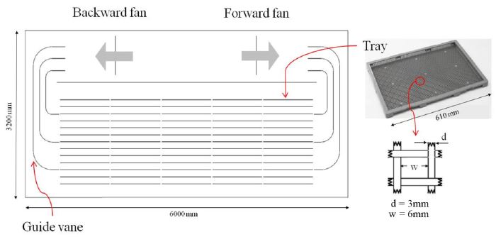
Drying chambers of the box type heat pump drying system were simplified and numerical calculation was performed in the two-dimensional domain (Fig. 1). The dryer is composed of a reverse direction fan, a forward direction fan, a guide vane, and 65 trays. The commercial software ANSYS-FLUENT was used for numerical analysis. The standard k-ε model was used as the turbulence model and the SIMPLE algorithm was used to analyze velocity-pressure coupling. To impose the flow conditions generated by the fans in the dryer, interior fan boundary conditions were used. Pressure differences arising from the inflow and outflow of air through a cross section of the fan were applied as boundary conditions; however, it was not necessary to calculate complex flow around the rotating fan blades. The relationship between the pressure difference and flow velocity through the fan is imposed from the performance curve corresponding to actual fan used in practical systems (Fig. 2). Calculation results showed that the velocities and pressure differences across the fan (expressed as the large square symbol in Fig. 2) satisfied the imposed fan performance curve. The computational mesh was comprised of quadrilateral cells and the number of grid cells used in the calculation was about 65,000.
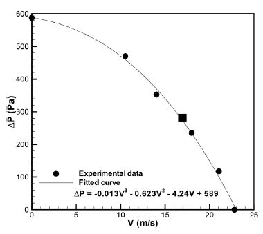
Fan performance curve: typical operation condition from the present numerical simulation is denoted by the square symbol
The base of the tray on which the materials are to be dried is made of a screen mesh. This study analyzed the flow through the tray by simplifying the mesh shape of the tray into a porous medium and applying Darcy’s law (Eq. 1) instead of directly modeling the shape of the tray.
| (1) |
P is the pressure, K is the permeability of the tray, μ is fluid viscosity, and v is fluid velocity.
Because the present analyses are two-dimensional, Eq. (1) can be simplified to the following Eq. (2):
| (2) |
δy is the thickness of porous media and δP is pressure difference across the tray. Permeability of the screen mesh can be found through the following Eq. (3-5):[9]
| (3) |
| (4) |
| (5) |
d is diameter of fiber, w is the width between two fibers, and the permeability of the tray installed in the practical dryer is K = 3.7 × 10⁻⁷ (m2).
3. Results and Discussion
3.1 Effects of the guide vanes
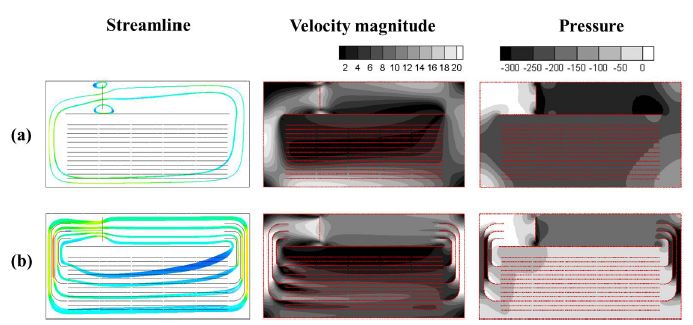
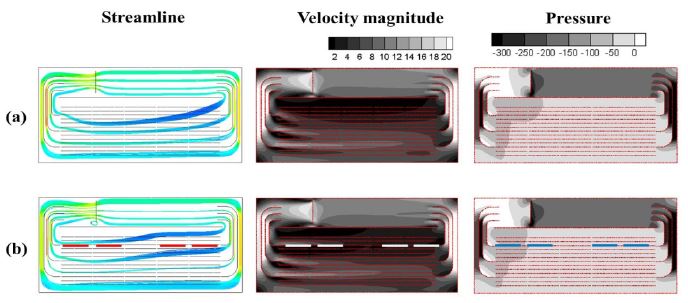
Figure 3a shows flow fields in the drying chamber in which guide vanes are not installed. Flow from the reverse direction fan moves along the wall of the drying chamber due to centrifugal forces of the curved streams; as a result, flow rate through the upper and middle trays is low and most of the flow is inclined toward the lower area of the drying chamber. As confirmed in the streamline, velocity distribution indicated that velocity was low at the upper and middle trays. From these results, it is estimated that materials on the upper and middle trays is not effectively dried. To solve the inhomogeneity of flows, guide vanes were installed in the drying chamber. By observing the flow patterns (Fig. 3b) in the drying chamber in which guide vanes are installed, it can be confirmed that, in this case, flow velocity increased more at the upper and middle trays than when the guide vane was not installed. Thus, it was verified that the installation of the guide vane enhanced the flow uniformity in the drying chamber; however, flow supply to the upper trays was still insufficient.
3.2 Effects of the solid plates
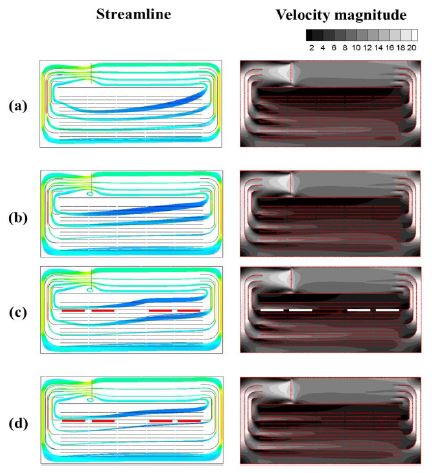
To effectively supply flow to upper trays, a solid plate was installed below the tray, located near the exit of the upper area of the guide vane (indicated as a thick line in Fig. 4b). Distribution of streamlines confirmed that the flow rate to the upper tray increased because the solid plate blocked the flow to the lower tray, as expected. To compare the flow uniformity, contours of velocity magnitude and pressure were also displayed for the fan operating in reverse direction. The distribution of the velocity magnitude clearly indicates the increase in flow rate near the upper tray. Therefore, by installing the solid plate below the upper tray, uniformity of flows increased.
Changes to flow fields due to attachment of solid plate to the bottom of upper trays, denoted by thick lines in (b)
Tray permeability decreases when the materials to be dried are positioned on the tray. Thus, a case was analyzed in which tray permeability is 10% of the original value, to identify the flow pattern in the drying chamber when the materials to be dried are positioned on the tray. From the streamlines in Figs. 5a and b, it was found that flow to the lower area through the upper tray significantly decreased when tray permeability was low, thereby leading to an increase in velocity at the area of the upper tray. Flows around the lower tray areas were nearly the same. Similar flow patterns were clear in the case with installation of the solid plate below the upper tray (Figs. 5c and d); however, the difference was insignificant to the case without the solid plate.
4. Conclusions
This study performed two-dimensional computational analyses on the internal flow pattern in a drying chamber to determine design conditions for uniform flow pattern of a large-capacity box type dryer. Fan boundary conditions based on the fan performance curve were applied to the internal flow of the dryer, and the tray with screen mesh on the bottom was simplified as a porous medium. It was confirmed that flow uniformity was enhanced in the drying chamber after the guide vane was installed, whereas flow was insufficiently supplied to the upper tray. To solve this problem, flow to the lower tray was induced to the upper tray by installing a solid plate, thereby ensuring a more uniform flow field.
Nomenclature
| P : | pressure, Pa |
| K : | permeability of the tray, m2 |
| μ : | fluid viscosity, kg/m・s |
| v : | fluid velocity, m/s |
| δy : | the thickness of porous media, m |
| ΔP : | pressure difference across the tray, Pa |
| d : | diameter of fiber, m |
| w : | width between two fibers, m |
Acknowledgments
This work was supported by the Korea Institute of Energy Research (KIER) grant (No. KIER-B4-2471).
References
- Eom, Y.-K., Ahn, D.-W., Cheon, S.-K., Seo, T.-W., (2006), “Flow Analysis to Develop Uniform Thermal Flow Distributions of the Box Type Dryer for Agriculture Products”, Korean Journal Of Air-Conditioning and Refrigeration Engineering, 18, p7-16.
-
Norton, T., Sun, D.-W., (2006), “Computational fluid dynamics (CFD)–an effective and efficient design and analysis tool for the food industry: a review”, Trends in Food Science & Technology, 17, p600-20.
[https://doi.org/10.1016/j.tifs.2006.05.004]

-
Scott, G., Richardson, P., (1997), “The application of computational fluid dynamics in the food industry”, Trends in Food Science & Technology, 8, p119-24.
[https://doi.org/10.1016/S0924-2244(97)01028-5]

-
Xia, B., Sun, D.-W., (2002), “Applications of computational fluid dynamics (CFD) in the food industry: a review”, Computers and electronics in agriculture, 34, p5-24.
[https://doi.org/10.1016/S0168-1699(01)00177-6]

-
Mirade, P.-S., (2003), “Prediction of the air velocity field in modern meat dryers using unsteady computational fluid dynamics (CFD) models”, Journal of Food Engineering, 60, p41-8.
[https://doi.org/10.1016/S0260-8774(03)00009-8]

-
Margaris, D.P., Ghiaus, A.-G., (2006), “Dried product quality improvement by air flow manipulation in tray dryers”, Journal of Food Engineering, 75, p542-50.
[https://doi.org/10.1016/j.jfoodeng.2005.04.037]

-
Mathioulakis, E., Karathanos, V., Belessiotis, V., (1998), “Simulation of air movement in a dryer by computational fluid dynamics: application for the drying of fruits”, Journal of Food Engineering, 36, p183-200.
[https://doi.org/10.1016/S0260-8774(98)00026-0]

-
Amanlou, Y., Zomorodian, A., (2010), “Applying CFD for designing a new fruit cabinet dryer”, Journal of Food Engineering, 101, p8-15.
[https://doi.org/10.1016/j.jfoodeng.2010.06.001]

- Lefèvrea, F., Conrardya, J.-B., Raynaudb, M., Bonjoura, J., (2011), “A Flat Plate Heat Pipe with Screen Meshes for the Cooling of Electronic Components”, 10th International heat pipe symposium, Taipei, Taiwan, p29-34.
