Print publication date 25 Sep 2023
제로에너지단지의 적정 수소 활용 규모 및 운용방식에 관한 연구
Copyright © 2023 by the New & Renewable Energy
This is an Open Access article distributed under the terms of the Creative Commons Attribution Non-Commercial License (http://creativecommons.org/licenses/by-nc/3.0) which permits unrestricted non-commercial use, distribution, and reproduction in any medium, provided the original work is properly cited.
Abstract
This study aims to evaluate the optimal size of the hydrogen facility to be installed in a zero-energy district in terms of load matching and facility efficiency. A mismatch between energy generation and consumption is a common occurrence in zero-energy districts. This mismatch adversely effects the energy grid. However, using an energy carrier such as hydrogen can solve this problem. To determine the optimal size of hydrogen fuel cells to be used on-site, simulation of hydrogen installation is required at both district- and building- levels. Each case had four operating schedules. Therefore, we evaluated eight scenarios in terms of load matching, heat loss, and facility operational efficiency. The results indicate that district-level installation of hydrogen facilities enables more efficient energy use. Additionally, based on the proposed model, we can calculate the optimal size of the hydrogen facility.
Keywords:
Net-zero energy district, District energy planning, Hydrogen fuel cell키워드:
제로에너지단지, 지구 단위 에너지 계획, 수소연료전지1. 서 론
2018년 한국의 국가 온실가스 배출량 총 727.6백만 톤CO2eq 중 건물부문 배출량은 약 171.9백만 톤CO2eq로 전체의 약 23.6%를 차지한다. 이 중 직접배출량은 약 48.9백만 톤CO2eq, 간접배출량은 약 122.9백만 톤CO2eq에 해당한다.[1] 2023년에 발표된 2050 탄소중립 녹색성장 국가전략 및 제1차 국가기본계획은 건물부문에서 2050년까지 직접 배출량의 약 88.1%, 2030년까지 약 32.8%를 감축하는 목표를 세웠으며, 전환부문의 중장기 감축을 위해 수요 효율화 혁신에도 기여하도록 하고 있다.[2] 세부적으로 국토교통 탄소중립 로드맵은 건물부문 탄소중립 핵심과제로 제로에너지건축물의 신축, 기존 건축물의 그린리모델링, 에너지효율 향상, 그리고 탄소중립도시와 같은 공간단위 탄소중립 전략을 세우고 있다.[3] 특히 탄소중립도시는 이 연구의 주요 대상인 ZED(Net Zero Energy District: 제로에너지단지)나 수소도시 모델을 포함한다.
ZED는 제로에너지건물의 에너지중립의 단위를 개별 건물에서 단지 차원으로 확대한 것으로, 다양한 지역 내 신재생에너지 잠재량을 활용하여 시설 규모를 확대하거나 공급방식을 다양화하여 효율성을 높일 수 있다.[4]
2019년 발간된 IEA 보고서는 고밀 정주환경에서 수소의 직간접 활용을 통해 장기적인 에너지 전환에 기여할 수 있음을 언급하고 있다.[5] Mazloomi and Gomes(2012)는 분산된 신재생에너지 발전원에서 비첨두 시간대에 생산된 전기에너지를 전달하는 매개체로서 수소의 효용성이 있음을 실증하였다.[6] Cao and Alanne(2015)은 제로에너지건축물에서 연료전지와 수소차를 활용한 에너지자립도를 분석하였다.[7] Jung et al.(2023)은 수소와 전기에너지를 활용한 제로에너지건축물 조성에 대해 연구하였고,[8] Wu and Zhong(2023)은 주거용건물에서 저장매체로서의 수소 활용에 대한 연구를 하였으나[9] 개별 건축물 단위에서의 고찰이었다는 한계가 있었다.
이 연구에서는 수소 활용의 범위를 건축물 단위뿐 아니라 서로 다른 용도의 건물들이 혼재된 단지 단위로 확장하고, ZED의 적정 수소 활용 규모를 산정하고자 하였다. 특히 수소 설비의 에너지이용효율을 높이는 동시에, ZED 내의 신재생에너지 생산과 수요 불일치에 따른 전력망 불안 해소에 기여할 수 있도록, 모델 경계 범위 내에서 생산된 전력의 활용 비중, 설비 유휴율, 잉여열 비중 등을 비교 평가지표로 사용하고자 하였다.
2. 연구 방법
2.1 연구의 범위
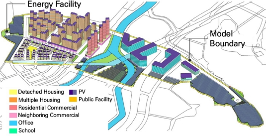
이 연구는 주거와 상업이 복합된 약 359,000 m2의 신규 택지개발구역을 대상으로 하며, 개별 건축물은 모두 제로에너지건축물 1등급 수준을 가정하였다. 연구 대상 지역의 구체적인 범위와 건축물 규모는 Fig. 1과 같으며, 해당 지역의 지구단위계획에 따라 Table 1과 같이 건축물 용도를 구성하였다.
ZED는 이 연구에서 Fig. 3에서 정의된 넷제로 평가 범위(Net Zero Energy Target Boundary)의 단위면적당 1차에너지 소비량과 단위면적당 1차에너지 생산량이 같은 단지로 정의되며, 식 (21)의 NPD 값이 1보다 커질 때 조건을 만족한다. 이때, 1차에너지 환산계수는 전력은 2.75, 연료전지에서 발생하는 열은 0으로 적용하였는데, 외부에서 공급되는 수소의 1차에너지환산계수가 향후 수소 생산 기술 개발 동향에 따라 크게 달라질 수 있기 때문에, 수소연료전지(이하 HFC) 발전량 중심으로 ZED 수지를 평가하고 열은 부산물로써의 폐열이용으로 간주하여 그 영향을 최소화하고자 하였다.
단지 내의 에너지 수요와 생산은 1년을 단위로 시간별로 평가하였다. 개별건축물 수준에서는 부지 외 생산을 허용한 냉난방, 급탕, 환기, 조명에너지에 대한 제로에너지건축물을 가정하였기 때문에, ZED의 평가 범위에는 추가로 전열 수요를 포함하였다. EV의 수요는 제로에너지단지의 평가 범위에는 포함하지 않았으나, 향후 탄소중립로드맵에 따른 전력망에 대한 부담을 고려하여 100% EV전환을 가정하고, 전력 수급 균형 평가에는 포함하였다.
단지 내 전기 생산 설비는 태양광과 HFC를 고려하였다. HFC는 연구의 시나리오에 따라 건물 단위 또는 단지 단위로 설치하는 것으로 가정하였으며(Table 3 참조), 설비의 규모는 변수로 두었다. 태양광 설비는 저층 건축물은 지붕 전체 면적에 적용하였고, 고층 건축물은 전전화(全電化) 시의 연간 냉난방, 급탕, 환기, 조명에너지 수요에 추가로 전열 수요를 포함하여 넷제로로 만드는 수준에서 지붕 및 단지 내 유휴부지에 설치하는 것으로 가정하였다.
모델 범위 외부로부터의 에너지 공급은 전기와 수소만으로 제한하였고, 개별 건축물은 전기와 열(냉열)을 사용하게 된다.
2.2 연구의 방법
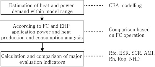
이 연구의 흐름은 다음 Fig. 2와 같다.
먼저 UBEM(Urban Building Energy modeling:도시 단위 건축물 에너지 모델링) 프로그램 중 하나인 CEA(City Energy Analyst)를 활용하여 모델 범위의 건축물 에너지 수요 및 PV 생산 잠재량을 예측하였다. CEA는 도시의 에너지 시스템 분석을 위한 오픈소스 소프트웨어로, 건물, 토지 이용 계획, 지역 냉난방, 재생에너지가 근린지역 및 지구 단위의 에너지 소비에 미치는 영향을 분석하기 위해 스위스 연방공과대학에서 개발하였다.[10] CEA의 에너지 수요 해석 모델은 EN ISO 13790:2008에 따라 simply hourly dynamic method를 사용하고 있다.[10,11]
이 연구는 2050년까지의 지속적인 효율화 및 EV 전환을 가정하여, 조례에 규정된 주차장 설치 기준에 따라 차량의 EV 충전 수요를 예측하거나, IEA(2021)의 2050 에너지부문 탄소중립 로드맵에 따른 전열 효율 개선 전망을 모델 범위 내의 에너지 수요 예측에 반영하였다.[12] Table 2는 이 연구의 에너지 해석을 위한 주요 가정이다.
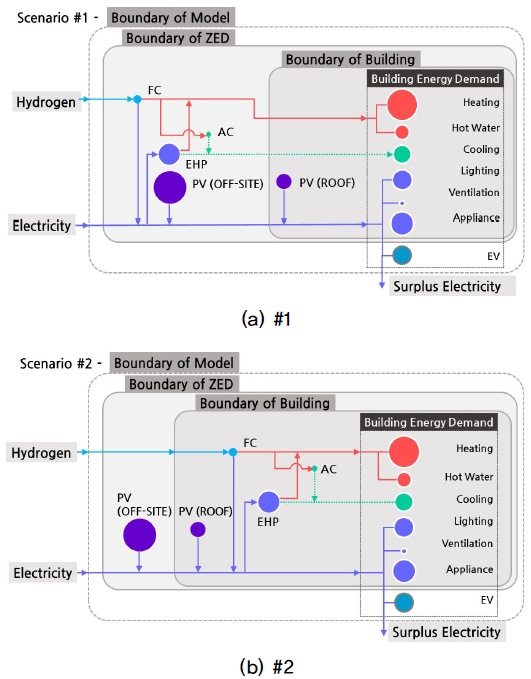
HFC는 설치 단위에 따라 단지 단위와 건물 단위 두 가지 시나리오로 구분하여 운용효율을 비교 분석하고자 하였으며(Table 3 참조) 각 시나리오의 에너지시스템은 Fig. 3과 같이 구성된다. 단지 단위 시나리오(#1)의 경우 단지 내 한 개 이상의 에너지 생산시설에 HFC와 EHP를 공동으로 설치하고 단지 전체의 열부하와 전력부하에 대응하는 운용방식을 가정한다. 개별 건물 단위 시나리오는 HFC와 EHP를 각 건물에 설치하고 개별 건축물의 열부하 및 전력 부하에 대응하여 독립적으로 운영하는 것을 가정한다.
HFC의 운용방식은 Table 4에 정의된 바와 같이, 4가지로 구분하였고, 부족한 열에너지소요량은 EHP를 가동하여 공급하였다. 4가지 운용방식 시나리오에서 HFC의 용량과 운용방식을 결정하는 열과 전력부하는 HFC의 출력변동 특성을 고려하여 일주일 평균으로 설정하였다. HFC의 설치 용량은 시나리오별 피크 전력수요와 비교하여 실제 설치되는 HFC의 비중인 Rpfc를 0~100% 범위 내에서 변화시켜 시뮬레이션하였으며, Table 5의 주요 평가지표가 최적화되는 점의 Rpfc를 ZED 계획시 적정 수소 도입 규모를 산정하는 기준으로 활용하고자 하였다. HFC의 효율은 D사 440 kW 수소 PAFC 제원을 따르되, 향후 기술개발을 가정하여 용량 변화를 허용하고, 건물 단위 HFC 설치 필요 용량 1 kW 미만 시에만 설치하지 않는 것으로 계산하였다.
시간당 필요한 총 전기에너지소요량 Etot은 식 (1)과 같이 계산되었다. Eap, Elight, Event, Hhs, Hhw, Hcs는 CEA 시뮬레이션을 통한 에너지 수요 예측값이다.
| (1) |
| (2) |
- Eap : 전열 및 취사 전기 에너지소요량(kWh)
- Elt : 조명 전기 에너지소요량(kWh)
- Evt : 환기 전기 에너지소요량(kWh)
- Eehp : EHP 전기 에너지소요량(kWh)
- Eev : EV 전기 에너지소요량(kWh)
- Hhs : 난방에너지(열) 요구량(kWh)
- Hhw : 급탕에너지(열) 요구량(kWh)
- Hcs : 냉방에너지(냉열) 요구량(kWh)
- rehph : 전체 열에너지요구량 중 EHP 공급비중
- rehpc : 전체 냉열에너지요구량 중 EHP 공급비중
시간당 요구되는 열에너지요구량 Htot는 식 (3)과 같고, CEA를 통해 산출된 냉난방, 급탕에너지 요구량으로부터 계산된다.
| (3) |
- cac : 흡수식냉동기 성능계수
Fm은 설치 HFC 용량을 최대 출력으로 가동할 때 소요되는 수소에너지량이며 식 (4)와 같이 계산된다. Fop는 운용 시나리오에 따른 FC가동에 필요한 수소에너지소요량이다. Fop는 운용시나리오별로 식 (5)와 같이 산출된다. 설치된 HFC 용량이 운용시나리오에 따른 수요보다 적을 경우, HFC는 최대 출력으로 운전하므로, 실제 FC 운전에 소요되는 수소에너지소요량 Ftot는 식 (6)과 같이 계산된다.
| (4) |
| (5) |
| (6) |
- Emax : 모델 범위 내 최대 전기에너지소요량(kWh)
- Fop : 운용시나리오에 따른 수소에너지소요량(kWh)
- Fm : HFC 최대 출력 시의 수소에너지소요량(kWh)
HFC 운용 시 잉여 열량 Hsp은 식 (7)과 같다.
| (7) |
- ηh : HFC 열 회수 효율
Ftot × ηh - Htot ≤ 0일 때, EHP로 공급되는 부족한 열량은 난방 및 급탕과 냉방에 대해 각각 Hdch과 Hdcc로 식 (8)과 식 (9)와 같이 정의된다.
| (8) |
| (9) |
따라서 전체 열에너지요구량 중 EHP 공급 비중 rehph와 전체 냉열에너지요구량 중 EHP 공급 비중 rehpc는 식 (10)과 식 (11)과 같다.
| (10) |
| (11) |
각 시나리오의 시간당 HFC 발전량 Pfc는 식 (12)와 같이 산출되며, CEA 시뮬레이션에 따라 산출된 시간당 태양광 발전량 Ppv와 합하여 시간당 총 전력생산량 Ptot이 계산되었다(식 (13) 참조).
| (12) |
| (13) |
2.3 모델 평가 기준
Table 6은 ZED의 적정 수소 활용 규모 및 운용방식의 비교 평가 지표들(Table 5 참조)을 도출하기 위해 참조한 선행연구를 정리한 것이다. 이 연구들은 용어 정의에 다소 차이가 있기는 했지만, 연구 범위 내의 에너지 직접 생산 비중이나 생산된 에너지를 직접 소비하는 비중을 공통된 지표로 다루고 있어, 이 연구에서도 이를 각각 ESR과 SCR로 정의하고 주요 평가지표로 두었다. Hernandez-Nochebuena et al.(2021)[13]은 이 밖에 수소의 수전해 생산을 위한 소요 면적을 경제성 평가 지표로 다루었지만, 이 연구에서는 수소를 모두 부지 내에서 생산하는 것이 아니고, 태양광 설치 면적 등은 모든 시나리오에서 고정되어 있어 해당지표는 고려되지 않았다.
ESR과 SCR, AMI은 식 (14)~(16)과 같이 모델범위 내 시간당 총 발전량 Ptot과 시간당 총 전기에너지 소요량 Etot으로부터 계산된다.
| (14) |
| (15) |
| (16) |
연간 HFC의 열에너지 생산량 중 잉여열의 비율 Rsh는 다음 식 (17)과 같으며 연간 HFC 가동률 Rop는 식 (18)과 같다.
| (17) |
| (18) |
NPD는 Fig. 3의 ZED 범위 내의 1차에너지 소비량에서 1차에너지 생산량을 뺀 값으로, 식 (19)~(21)과 같이 정의된다. NPD가 0 kWh/m2면 ZED 범위 내에 넷제로에너지조건이 달성되며,0 kWh/m2보다 클 경우, 넷제로에너지조건이 달성되지 않아 추가로 외부에서 에너지를 도입해야하는 단지임을 의미한다.
| (19) |
| (20) |
| (21) |
- PEC : ZED 범위 내 총 1차에너지소비량(kWh)
- PES : ZED 범위 내 총 1차에너지생산량(kWh)
- AFA : 단지 내 총 연면적의 합
3. 연간 에너지 수요 예측
CEA를 활용한 건물 에너지 시뮬레이션 결과 모델 범위 내 연간 전기에너지 소요량 및 열에너지요구량, 태양광 발전량이 Table 7과 같이 도출되었다. 냉난방급탕에 필요한 열에너지소요량은 이 연구의 시나리오에 따른 HFC 설치규모에 따라 식 (2)와 식 (6)을 활용하여 열에너지요구량으로부터 EHP 전기에너지소요량 Eehp과 HFC 운전에 소요되는 수소에너지소요량 Ftot으로 산출된다. 따라서 UBEM 모델에서는 냉난방 및 급탕에너지요구량만을 계산하였다.
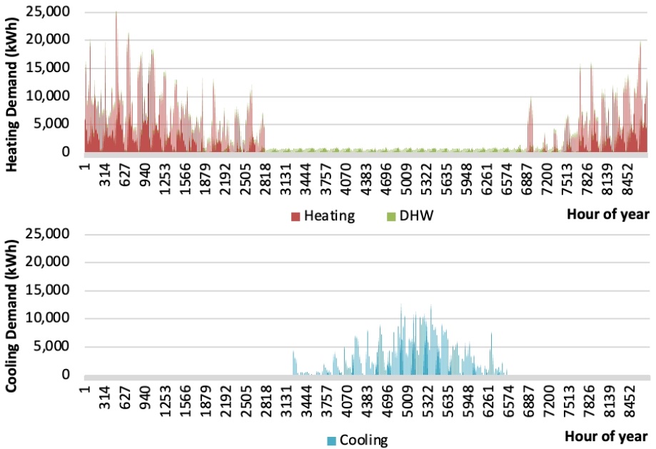
CEA 시뮬레이션을 통해 도출된 연간 시간당 전력 및 열 수요는 Fig. 4, 5와 같다. 시간별 태양광 발전량 및 전기에너지 소요량 변화를 고려할 때 해당 단지에 실시간 전력 부족 및 잉여가 발생하는 것으로 분석된다.
4. 결 과
다음은 모델 범위 내 전기 및 열에너지 수지 모델링을 통해 HFC 설치 규모와 운용방식에 따른 Table 5의 평가 지표들의 변화를 비교 분석한 결과이다.
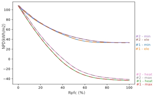
Fig. 6은 HFC 용량에 따른 NPD 변화를 나타내는 그래프이다. 넷제로 조건인 ‘NPD = 0’을 만족하는 HFC 설치 용량은 최대 부하를 기준으로 설치할 때의 HFC 용량 5.4 MW의 단지단위 설치 시 약 37%, 건물단위 설치 시 약 41% 규모로 나타난다. HFC 용량이 작을수록 NPD의 값은 점점 커져, HFC가 설치되지 않은 전력화 시나리오에서 가장 큰 값인 108 kWh/m2를 나타난다. 수소 도입 시나리오 중에는 같은 설치용량 대비 #2-ele와 #2-min에서 최소값이 나타나며, #1-ele, #1-min, #2-ele, #2-min의 경우 NPD값이 0 kWh/m2에 도달하지 못하여 넷제로를 달성하지 않았다.
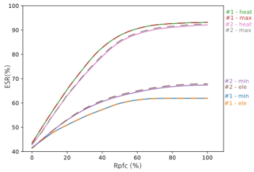
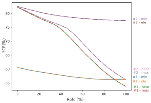
Fig. 7, 8에서 ESR의 값은 HFC의 용량에 비례하여 증가하는 경향을, SCR은 감소하는 경향을 보인다. 다만, ESR 값의 증가율은 HFC 증가에 따라 점차 감소하며, ele와 min-시나리오에서 ESR은 68%를 넘지 않았다.SCR은 ele와 min-시나리오에서 완만히 감소한 반면, #1-heat과 #-1max 시나리오에서는 Rpfc 68%, #2-max에서 63%, #2-heat에서는 61%가 넘으면, 발전량이 전기에너지소요량 수준을 넘겨 급격히 감소하였다.
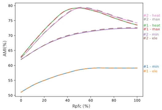
ESR과 SCR의 평균값인 AMI(Fig. 9 참조)는 heat과 max 시나리오에서 상대적으로 높았으며, #1-max와 #1-heat 시나리오에서는 Rpfc 54%를 정점으로, #2-heat 과 #2-max 시나리오에서는 Rpfc 58%를 정점으로 다시 감소하는 경향을 보였다.
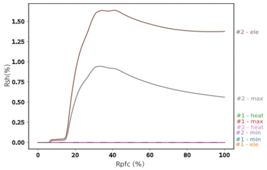
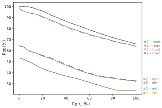
Fig. 10의 잉여열 비중 Rsh #2-ele와 #2-max 시나리오에서만 나타나며, 최대값은 #2-ele 시나리오의 Rpfc 40%일 때 1.64% 수준이었다. Fig. 11의 연간 HFC 가동률 Rop은 HFC 용량 증가에 따라 모든 시나리오에서 감소하는 추세였으며, #1-max와 #1-heat 시나리오에서는 Rpfc 12%까지 100%를 유지하였다. 반면, ele와 min 시나리오에서는 70%가 넘지 않아 제조사의 적정 운영효율을 유지하기에 불리한 것으로 나타난다.
Table 8은 넷제로 조건에서의 평가지표들을 분석한 결과로 Rpfc범위는 37~41%로 나타났으며, ‘NPD = 108 kWh/m2인 전력화 시나리오에 비해 (대조군 ctrl) HFC 도입이 ZED 조건 달성에는 유리한 것으로 보인다. 또한 ESR, SCR, AMI에서 비교우위를 보여 단지 내 전력망 안정성에도 기여할 수 있는 것으로 해석된다. heat과 max 시나리오에서, 건물 단위 시나리오 대비 단지 단위 시나리오에서 비교적 작은 Rpfc로 넷제로를 달성하였다.
최대 AMI를 기준으로 HFC의 규모를 산정하여 설치한 경우(Table 9 참조), ESR과 SCR, Rop은 모두 대조군과 비교하여 뚜렷이 증가하였다. 단지 단위 설치 시나리오 #1에서는 같은 운용방식에서 건물 단위 설치 시나리오 #2 대비 Rpfc는 상대적으로 작게 나타났다. #1-heat과 #1-max 시나리오에서 AMI와 Rop 값이 가장 높았다.
ZED 조건으로 HFC 설치 규모를 적용했을 때와 비교하여 최대 AMI 조건으로 HFC 설치 규모를 적용하였을 경우, Rpfc가 커지면서 Rop는 다소 낮아지는 경향을 보였다. min과 ele시나리오는 모든 조건에서 가동률 Rop이 70%를 넘지 못했다. HFC를 단지 단위로 Rpfc 52% 규모로 설치하여 열부하 중심으로 운용하는 것이(#1-heat) 최소의 설비로 가동률을 가장 높여 운영하는 동시에, 전력망 안정화에 대한 기여도도 가장 높은 것으로 평가되었다. 단위연면적당 HFC 설치 규모는 약 0.0069 kWp/m2 수준이다. 건물 단위로 HFC를 설치하여 열부하 중심으로 운전하는 시나리오는 (#2-heat) AMI 값은 단지단위 열부하 중심 운용 시나리오와 거의 같은 값이 나왔지만, HFC를 설치 규모가 Rpfc 54% 수준, 단위연면적당 약 0.0072 kWp/m2으로 다소 증가하면서 가동률은 약 77%정도로 다소 낮게 나타났다. 전반적으로 ESR은 단지단위가, SCR은 건물단위가 좀더 유리한 것으로 나타났다. 최대 AMI 조건에서 단지단위와 건물단위 열추종 시나리오와 최대부하 시나리오는 NPD가 모두 음(-)의 값을 갖는 플러스에너지단지로 나타나는 데, 모델에서 건물의 에너지수요 외에 추가로 EV 수요가 고려된 결과로 보여진다.
5. 결 론
이 연구는 모델 범위 내 소비전력의 자립도, 생산전력의 자가소비율, 투입수소 대비 잉여열 손실, HFC 가동률, ZED 조건만족을 위해 추가로 투입되어야 하는 단위연면적당 수소에너지량의 지표를 중심으로 ZED를 위한 적정 수소에너지 활용 규모 산정 및 운용방식 비교 분석하였다. 분석결과는 다음과 같다.
HFC의 도입은 전력화 시나리오와 비교하여 전력자립율 향상에 기여할 뿐 아니라 연료전지 폐열 이용을 통해 ZED 조성에도 유리한 것을 확인하였다. ZED 조건의 평가는 HFC 공급되는 수소의 종류에 따라 달라질 여지가 있으나, HFC를의 활용은 단지 내 직접 에너지생산을 증가시켜 PV 설치 면적을 줄일 수 있으므로 토지이용 효율 개선 및 토지비용을 고려한 경제성 평가에 이점이 있을 것으로 보인다.
운용시나리오 별로는 전력부하 중심과 최소부하 중심 시나리오에서 연간 평균 HFC 가동률이 70% 미만으로 낮게 나타나 HFC의 효율적인 운용이 어려운 것으로 보이며, 전력자립도 증가에 미치는 영향도 제한적인 것으로 분석된다. 반면, 열부하와 최대 부하 중심 시나리오가 전력자립도에 대한 기여 가능성이 높았으며, 전력망에 대한 기여도가 같을 때 상대적으로 작은 설비규모에서 높은 가동률로 운영될 수 있음을 확인하였다.
단지단위 시나리오가 전력자립도와 가동률면에서 건물단위 시나리오보다 전반적으로 높은 값을 보였지만, 생산된 전력의 자가소비비중은 건물단위 시나리오에서 좀 더 유리하게 나타났다.
이 연구는 HFC 설치가 제로에너지단지 설계에서 모델 범위 내의 에너지 수급 및 전력망 불안 해소에 미치는 영향을 정량적으로 비교 분석하여 적정 규모 및 운영방식을 계획할 수 있는 방법론을 제시하였다는 점에서 의의가 있다. 그러나 HFC의 폐열 활용을 우선하는 것으로 가정하여, EHP 설비의 유휴율을 통합적으로 고려하지 않았다는 한계가 있다. 수소 설비 도입의 경제성은 수소와 수소설비의 미래가격 등 불확실한 요소가 많아 이 연구의 범위 내에서 평가하기는 어려우나, 앞으로 ESS와 같은 전력수급 불균형 해소에 기여할 수 있는 다른 기술과의 비교 우위나 ZED 범위 내 추가 수소생산설비 도입과 PV 설치 규모사이의 최적화 비율 산정을 위해 경제성 평가를 포함하는 후속연구가 필요하다. 건축물 용도 비중의 변화에 따른 수요 평탄화 가능성이 HFC 규모 및 운용방식에 미치는 영향이나 HFC와 비교하여 탄력적인 운용이 가능한 수소 열병합 발전의 도입도 앞으로 연구해야 할 과제이다.
Nomenclature
| EHP : | electric heat pump |
| HFC : | hydrogen fuel cel |
| Etot : | hourly total electricity demand (kWh) |
| Htot : | hourly total heat demand (kWh) |
| Ftot : | hourly total hydrogen demand (kWh) |
| Ptot : | hourly total electricity generation (kWh) |
| Hsp : | hourly heat surplus (kWh) |
| Hdch : | hourly heat deficit in heat demand (kWh) |
| Hdcc : | hourly heat deficit in cooling demand (kWh) |
| Ppv : | hourly electricity production by PV (kWh) |
| Pfc : | hourly electricity production by FC (kWh) |
| Kfcm : | fuel cell capacity installed in each scenario (kW) |
| ESR : | Electricity Self-sufficiency rate (%) |
| SCR : | Electricity Self–Consumption rate (%) |
| AMI : | averaged matching index (%) |
| RK : | fuel cell capacity ratio in total heat supply (%) |
| Rpfc : | ratio of fuel cell modules installed to maximum installed fuel cell modules that meet peak electricity demand (%) |
| Rsh : | ratio of surplus heat (%) |
| Rop : | operating rate of fuel cells (%) |
| NPD : | net primary energy demand per unit area (kWh/m2) |
| t : | hour of year |
Acknowledgments
이 연구는 2021년도 산업통상자원부 재원으로 한국에너지기술평가원(KETEP)의 탄소중립 사회구현을 위한 수소 기반 에너지 체계 구축 방안 연구 사업으로 지원받아 수행되었습니다(No. 20213030030270).
References
- Greenhouse Gas Inventory & Research Center of Korea, 2020, “Greenhouse gas inventory by region based on metropolitan local governments(1990-2018), official”, http://www.gir.go.kr/home/board/read.do?pagerOffset=0&maxPageItems=10&maxIndexPages=10&searchKey=&searchValue=&menuId=36&boardId=52&boardMasterId=2&boardCategoryId=, .
- Korean Government, 2023, “Carbon neutral/green growth national strategy and 1st national basic plan”, https://www.2050cnc.go.kr/download/BOARD_ATTACH?storageNo=2031, .
- Ministry of Land, Infrastructure and Transport, 2021, “Roadmap for carbon neutrality in land, Infrastructure and transport”, http://www.molit.go.kr/USR/NEWS/m_71/dtl.jsp?lcmspage=1&id=95086352, .
- Kim, M.K. and Kim, M.Y., 2011, “Zero energy town: Concept and policy case study”, Seoul Studies., 12(1), 159-180.
- International Energy Agency(IEA), 2019, “The Future of Hydrogen”, IEA, Paris, https://www.iea.org/reports/the-future-of-hydrogen, .
-
Mazloomi, K. and Gomes, C., 2012, “Hydrogen as an energy carrier: Prospects and challenges”, Renewable and Sustainable Energy Reviews, 16(5), 3024-3033.
[https://doi.org/10.1016/j.rser.2012.02.028]

-
Cao, S. and Alanne, K., 2015, “Technical feasibility of a hybrid on-site H2 and renewable energy system for a zero-energy building with a H2 vehicle”, Applied Energy, 158, 568-583.
[https://doi.org/10.1016/j.apenergy.2015.08.009]

-
Jung, Y., Heo, Y., Cho, H., Kang, Y.T., Kim, Y., and Lee, H., 2023, “A plan to build a net zero energy building in hydrogen and electricity-based energy scenario in South Korea”, J. Clean. Prod., 397, 136537.
[https://doi.org/10.1016/j.jclepro.2023.136537]

-
Wu, Y. and Zhong, L., 2023, “An integrated energy analysis framework for evaluating the application of hydrogen-based energy storage systems in achieving net zero energy buildings and cities in Canada”, Energy Convers. Manag, 286, 117006.
[https://doi.org/10.1016/j.enconman.2023.117066]

- City Energy Analyst(CEA), 2023, “The city energy analyst documentation (Version 3.32.0)”, Accessed 09 June 2023, https://city-energy-analyst.readthedocs.io/_/downloads/en/latest/pdf/, .
-
Fonseca, J.A. and Schlueter, A., 2015, “Integrated model for characterization of spatiotemporal building energy consumption patterns in neighborhoods and city districts”, Applied Energy, 142, 247-265.
[https://doi.org/10.1016/j.apenergy.2014.12.068]

- IEA, 2021, “Net Zero by 2050 – A Roadmap for the Global Energy Sector”, Paris, https://www.iea.org/reports/net-zero-by-2050, .
-
Hernánandez-Nochebuena, M.A., Cervantes, I., and Araujo-Vargas, I., 2021, “The effect of the energy interchange dynamics on the zero-energy hydrogen economy of households with FC hybrid electric vehicles”, Int. J. Hydrog, 46(40), 21160-21181.
[https://doi.org/10.1016/j.ijhydene.2021.03.233]

-
Cao, S., Klein, K., Herkel, S., and Sirén, K., 2017, “Approaches to enhance the energy performance of a zero-energy building integrated with a commercial-scale hydrogen fueled zero-energy vehicle under Finnish and German conditions”, Energy Conversion and Management, 142, 153-175.
[https://doi.org/10.1016/j.enconman.2017.03.037]

-
Millet, L., Berrueta, A., Bruch, M., Reiners, N., and Vetter, M., 2019, “Extensive analysis of photovoltaic battery self-consumption: Evaluation through an innovative district case-study”, Applied Physics Reviews, American Institute of Physics Inc., 6(2).
[https://doi.org/10.1063/1.5049665]

-
Liu, J., Cao, S., Chen, X., Yang, H., and Peng, J., 2021, “Energy planning of renewable applications in high-rise residential buildings integrating battery and hydrogen vehicle storage”, Applied Energy, 281, 116038.
[https://doi.org/10.1016/j.apenergy.2020.116038]

-
Tercan, S.M., Demirci, A., Gokalp, E., and Cali, U., 2022, “Maximizing self-consumption rates and power quality towards two-stage evaluation for solar energy and shared energy storage empowered microgrids” J. Energy Storage, 51, 104561.
[https://doi.org/10.1016/j.est.2022.104561]


