Online publication date 15 Mar 2022
고효율 TOPCon 태양전지의 SiOX/poly-Si박막 형성 기법과 passivating contact 특성
 ; Taeyong Kim2)
 ; Sungjin Jeong3)
 ; Yewon Cha3)
 ; Hongrae Kim3)
 ; Somin Park3)
 ; Minkyu Ju4)
 ; Junsin Yi4), *
Copyright © 2022 by the New & Renewable Energy
This is an Open Access article distributed under the terms of the Creative Commons Attribution Non-Commercial License (http://creativecommons.org/licenses/by-nc/3.0) which permits unrestricted non-commercial use, distribution, and reproduction in any medium, provided the original work is properly cited.
Abstract
The most prevalent cause of solar cell efficiency loss is reduced recombination at the metal electrode and silicon junction. To boost efficiency, a a SiOX/poly-Si passivating interface is being developed. Poly-Si for passivating contact is formed by various deposition methods (sputtering, PECVD, LPCVD, HWCVD) where the ploy-Si characterization depends on the deposition method. The sputtering process forms a dense Si film at a low deposition rate of 2.6 nm/min and develops a low passivation characteristic of 690 mV. The PECVD process offers a deposition rate of 28 nm/min with satisfactory passivation characteristics. The LPCVD process is the slowest with a deposition rate of 1.4 nm/min, and can prevent blistering if deposited at high temperatures. The HWCVD process has the fastest deposition rate at 150 nm/min with excellent passivation characteristics. However, the uniformity of the deposited film decreases as the area increases. Also, the best passivation characteristics are obtained at high doping. Thus, it is necessary to optimize the doping process depending on the deposition method.
Keywords:
Passivation, TOPCon, poly-Si, SiOx, Deposition method키워드:
패시베이션, 탑콘, 다결정실리콘, 실리콘산화막, 증착 방법1. 서 론
태양전지는 조사된 빛에 의해 electron과 hole이 생성되고 carrier selectivity에 의해 양 전극으로 carrier가 이동하게 된다. 실리콘 기반 태양전지의 일반적인 구조인 Al-BSF에서는 metal-silicon 계면에서 interface defect으로 인해 재결합이 손실이 크게 나타난다. 고효율 태양전지를 제작하기 위해서는 생성된 carrier의 재결합을 최소화해야 한다. 광흡수로 인해 생성된 EHP의 재결합을 최소화하여 효율을 향상시키는 방법으로 passivating contact에 대한 다양한 연구가 진행되고 있다.[1~2]
Fig. 1은 TOPCon에서 후면 passivating contact의 밴드다이어그램을 보여준다. Passivating contact은 금속과 실리콘 계면에서 재결합을 줄여주는 역할을 한다. n-type poly-Si의 doping 농도를 높게 할 경우, major carrier인 electron은 field effect으로 인해 금속 접합 부분으로 tunneling이 가능하지만, minor carrier인 hole은 tunneling 하지 못하고 선택적으로 전자를 수집할 수 있어 EHP의 재결합으로 인한 효율저하를 줄이고 개방전압을 향상시킬 수 있다.[3]
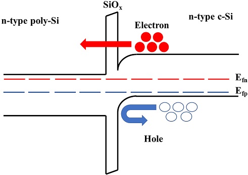
Sselective collection of electron via quantum-tunneling effect in rear side passivating contact of TOPCon solar cell
패시베이션 층으로는 hydrogenated a-Si와 silicon oxide(SiOX)가 주로 사용되고 있다. Intrinsic a-Si:H을 passivation 층으로 사용하는 구조를 heterojunction 또는 HJT라고 하며, SiOX를 passivation 층으로 사용하는 태양전지에서는 SiOX위에 poly-Si이 증착된 구조로 POLO, SIPOS, TOPCon이 있다.[2~7] 독일의 Fraunhofer Institute for Solar Energy System(ISE)에서는 TOPCon 구조로 25.7%의 효율을 기록하였다.[8]
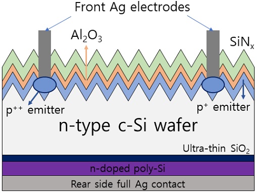
TOPCon 태양전지는 Fig. 2와 같이 태양전지 후면에 ultra thin SiOX와 고농도 poly-Si을 증착하여 passivating contact을 형성한 구조이다. Tunneling effect을 향상시키기 위해서는 poly-Si층의 doping 농도를 높이는 것이 중요하다. poly-Si을 형성하기 위한 대표적인 증착 방법으로는 화학기상증착(CVD)과 물리기상증착(PVD)이 있다. 많이 사용되는 증착 방법으로 CVD는 LPCVD,[9~11] PECVD,[8,12~14] HDPCVD, HWCVD[15]가 있으며, PVD는 electron beam evaporation, sputtering[16~17]이 있다. Poly-Si이 가지는 특성은 증착 방법과 poly-Si의 두께, doping 농도, 열처리 온도 및 시간에 따라 달라진다. poly-Si의 두께는 열처리시 in-diffusion을 방지 할 수 있을 정도로 충분히 두꺼워야 하지만 일정 두께 이상에서는 전류 손실이 발생할 수 있다. 열처리를 진행 할 경우 온도를 급격히 상승시키면 blistering현상으로 인해 결함이 발생해 막질에 영향을 줄 수 있다. 패시베이션 특성을 향상시키기 위해서는 poly-Si의 두께를 최적화 하고, 고농도 doping을 통해 filed effect 특성을 향상시켜 carrier를 수월하게 수집하게 만들어야 한다. poly-Si의 두께가 두꺼울수록 고농도의 poly-Si 박막을 증착하고 passivating contact을 형성하기 위해서는 증착 기술의 전반적인 필름 특성을 이해하는 것이 필요하다.[18~19]
본 논문에서는 TOPCon 태양전지에서 증착 방법에 따른 패시베이션 특성에 대해 비교할 것이다. Sputtering, PECVD, HWCVD와 LPCVD를 이용하여 증착한 poly-Si의 doping 속도와 농도, implied VOC를 비교하여 증착방법에 따라 패시베이션 특성의 차이에 대해 서술한다.
2. 실험방법
Polishing float-zone(FZ)(100)웨이퍼를 saw damage etching 후, standard RCA cleaning을 진행하였다. Thin SiOX 박막은 90℃의 질산을 이용하여 형성하였다. 증착 시 Sputtering의 RF 전력밀도는 3.1 W/cm2, 증착 온도와 압력은 각각 25℃와 2 mTorr이며, PECVD의 증착 온도와 압력은 300℃와 150 mTorr이고, SiH4/Ar의 가스유량은 20/20 sccm에서 증착하였다. HWCVD의 증착 온도와 압력은 각각 100℃와 450 mTorr이며, wire의 온도는 2000℃, PH3의 농도를 PH3/(SiH4+PH3)로 정의할 때, PH3의 농도가 2%인 혼합가스의 유량과 H2의 유량은 10 sccm이다. LPCVD는 증착 온도와 압력이 520℃와 250 mTorr이고, SiH4의 유량은 45 sccm인 환경에서 증착하였다. a-Si 또는 poly-Si을 증착 후 phosphorus 확산 도핑을 하였다. 열처리는 850~860℃에서 30분 동안 진행하였으며, 그 결과 생기는 phosphorus silicate glass(PSG)는 HF 용액을 이용해 제거하였다.
3. 실험결과 및 고찰
3.1 증착 속도 비교
Sputtering 방법은 플라즈마에 의해 높은 에너지를 가지는 Ar 이온이 Si 타겟에 충격을 가하면서 Si 원자를 생성하고 기판에 증착되는 방법으로 물리적인 증착방법이다. LPCVD 방법은 열을 이용해 반응가스를 분해하고 이동하여 웨이퍼 표면에 증착시키는 방법이다. PECVD 방법은 반응기체를 플라즈마 상태로 만들어 원하는 물질은 웨이퍼 표면에 증착하고 나머지는 밖으로 배출시키는 방법이다. HWCVD는 반응가스를 고온의 열선 표면에서 분해시키고 증착시키는 방법이다.
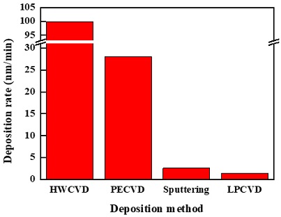
Fig. 3은 intrinsic a-Si(poly-Si)을 sputtering, PECVD, HWCVD, LPCVD를 이용해 증착 할 때, 증착속도를 보여준다. 증착 방법에 따라 증착 속도는 각각 2.6 nm/min, 28 nm/min, 150 nm/min, 1.4 nm/min이다. Sputtering 증착 방법은 2.6 nm/min으로 대체적으로 CVD보다 낮은 증착 속도를 보였다. Ar이온으로 생성된 Si 원자는 열적 활성화보다는 운동량 전달에 에너지를 소비하게 되므로 증착 속도가 CVD방법보다 느리다. 하지만 다른 증착 기법보다 조밀한 막을 형성 할 수 있다는 장점이 있다. LPCVD의 증착속도는 1.4 nm/min으로 증착 방법들 중에서 가장 낮았다. PECVD 보다 온도와 압력이 높은 조건이었지만 증착속도는 약 20배 더 느렸다. 이는 플라즈마를 이용할 경우 반응가스를 분해하는 속도가 열 분해를 이용할 때보다 빠르기 때문에 증착속도의 차이가 생긴다고 볼 수 있다. HWCVD와 비교했을 때에는 HWCVD의 압력이 200 mTorr 더 높았지만 온도는 상온에서 진행되었다. LPCVD와는 달리 챔버 전체를 고온의 환경으로 만들지 않고 열선만 고온으로 상용하기 때문에 반응가스는 열선 표면에서 일어나며 증착 속도는 70배 이상 차이 나는 것을 확인 하였다.
3.2 도핑농도 및 면저항 비교
캐리어 농도 조절로 surface recombination을 줄일 수 있다. 전자나 정공 중 하나의 캐리어 농도만 낮아도 recombination을 줄일 수 있다. 농도를 낮추기 위해서는 소수 캐리어를 밀어내는 전기장을 사용하는데 이를 field effect passivation이라고 한다.[20]
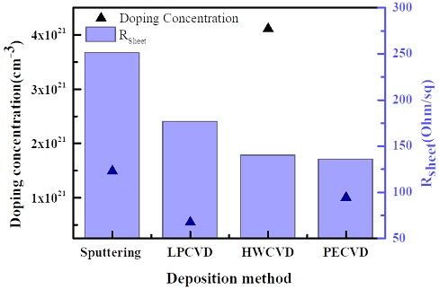
Fig. 4는 소개된 증착 기법을 사용하여 증착한 poly-Si의 phosphorus doping 농도와 면저항을 나타낸 그래프이다. HWCVD를 이용한 방법이 약 4×1021 cm-3로 가장 높은 doping 농도를 가졌으며 LPCVD로 증착한 poly-Si이 약 5×1020 cm-3으로 가장 낮은 doping 농도를 형성했다. 면저항은 sputtering을 이용한 증착 방법이 251 ohm/sq로 가장 높은 면저항을 나타냈으며, PECVD를 이용한 증착 방법에서 135 ohm/sq로 가장 낮은 면저항 특성을 나타냈다. 이후 열처리 과정에서 확산온도가 높아질수록 면저항은 감소하는 경향을 보이는 것을 확인하였다.[21~23]
3.3 패시베이션 특성 비교
Poly-Si은 solubility를 넘어서는 농도로 doping되면 c-Si으로 dopant가 in-diffusion되어 auger recombination이 증가하기 때문에 doping 농도가 증가할수록 iVOC가 감소한다.
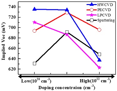
Fig. 5는 doping 농도가 증가함에 따라 iVOC의 값의 변화를 나타낸 그래프이다. 대체적으로 poly-Si은 doping 농도가 증가할 때 iVOC는 감소하는 경향을 보이는 것을 볼 수 있다. PECVD와 HWCVD 방법은 다른 공정 기법보다 증착시 수소의 양이 많아 annealing 과정에서 blistering이 발생하고 이로 인해 iVOC가 감소한다. Blistering은 고온에서 수소가 유착되거나 방출되면서 발생하는 현상으로 보고되었으며, 이 현상을 줄이기 위해 증착 온도를 높이거나 annealing 승온시간 조절을 통해 blistering을 제어할 수 있다.[24~26]
4. 결 론
본 논문에서는 sputtering과 PECVD, HWCVD, LPCVD를 이용해 형성한 poly-Si의 특성과 passivating contact의 특성을 비교, 분석하였다. HWCVD 증착 방법은 증착속도가 100 nm/min으로 가장 빨랐으며, LPCVD를 이용한 방법이 증착속도가 가장 느린 것으로 확인했다. poly-Si의 doping 농도 또한 HWCVD를 이용한 방법이 4×1021 cm-3으로 가장 높게 나왔으며, LPCVD를 이용한 방법이 5×1020 cm-3으로 가장 낮은 doping 농도를 형성하였다. 하지만 고농도로 doping하게 될 경우 HWCVD를 이용한 방법의 패시베이션 특성은 급격히 낮아졌으며, PECVD를 이용한 방법의 특성이 상대적으로 잘 유지되었다. Annealing 동안에 phosporous dopant가 c-Si 내부로 확산하는 in-diffusion 현상으로 인해 c-Si으로 in-diffusion된 농도는 LPCVD가 가장 높았으며, sputtering이 가장 낮은 in-diffusion doping 농도를 보였다. 각 공정에 따른 iVOC는 sputtering, PECVD, HWCVD, LPCVD 증착 방법 각각 690 mV, 729 mV, 735 mV, 710 mV으로 HWCVD가 가장 높은 iVOC값을 나타냈다. 패시베이션 특성은 poly-Si의 농도가 증가할수록 증착 방법과 각 공정의 조건에 따라 달라진다. Filed effect passivation 특성을 향상시키기 위해서는 고농도의 poly-Si을 증착해야한다. 하지만 doping 농도가 5×1021 cm-3이상 되면 열처리 후 실리콘 기판으로 dopant가 확산하고, blistering으로 인해 패시베이션 특성이 떨어진다. 증착 방법에 따라 열처리 후 dopant의 확산과 blistering을 제어할 수 있는 공정조건을 확립함으로써 태양전지의 효율을 향상시킬 수 있을 것으로 기대한다.
Subscript
| EHP : | electron-hole pair |
| Al-BSF : | aluminium back surface field |
| HIT : | heterojunction with intrinsic thin layer |
| TOPCon : | tunnel oxide passivated contact |
| POLO : | polycrystallince silicon on oxide |
| SIPOS : | semi-insulating polycrystalline silicon |
| CVD : | chemical vapor deposition |
| PVD : | physical vapor deposition |
| LPCVD : | low pressure chemical vapor deposition |
| PECVD : | plasma enhanced chemical vapor deposition |
| HWCVD : | hot wire chemical vapor deposition |
| iVOC : | implied open circuit voltage |
| c-Si : | crystalline silicon |
| a-Si : | amorphous silicon |
| poly-Si : | polycrystalline silicon |
Acknowledgments
이 연구는 2021년도 산업통상자원부 및 산업기술평가관리원(KEIT) 연구비 지원에 의한 연구(n-TOPCon 효율 최적화 pn 접합 형성을 위한 붕소(boron) 도핑(doping) 장비기술개발 소재부품/개발패 키지형 사업, 20016058), 2014년도 산업통상자원부 ‘산업혁신인재성장지원사업’의 재원으로 한국산업기술진흥원(KIAT)의 지원을 받아 수행된 연구임(2021년 차세대 디스플레이 공정・장비・소재 전문인력 양성사업, 과제번호 : P0012453).
References
-
Mitra, S., Ghosh, H., Saha, H., and Ghosh, K., 2019, “Recombination analysis of tunnel oxide passivated contact solar cells”, IEEE Trans Electron Devices, 66 (3), 1368-1376.
[https://doi.org/10.1109/TED.2018.2890584]

-
Masuko, K., Shigematsu, M., Hashiguchi, T., Fujishima, D., Kai, M., Yoshimura, N., Yamaguchi, T., Ichihashi, Y., Mishima, T., and Matsubara, N., et al., 2014, “Achievement of more than 25% conversion efficiency with crystalline silicon heterojunction solar cell”, IEEE J. Photovolt., 4(6), 1433-1435.
[https://doi.org/10.1109/JPHOTOV.2014.2352151]

-
Larionova, Y., Turcu, M., Reiter, S., Brendel, R., Tetzlaff, D., Krügener, J., Wietler, T., Höhne, U., Kähler, J.D., and Peibst, R., 2017, “On the recombination behavior of p+-type polysilicon on oxide junctions deposited by different methods on textured and planar surfaces”, Phys. Status. Solidi Appl. Mater. Sci., 214(8), 1700058.
[https://doi.org/10.1002/pssa.201700058]

-
Green, M.A., Dunlop, E.D., Levi, D.H., Hohl-Ebinger, J., Yoshita, M., and Ho-Baillie, A.W.Y., 2019, “Solar cell efficiency tables (version 54)”, Prog. Photovoltaics Res. Appl., 27(7), 565-575
[https://doi.org/10.1002/pip.3171]

-
Green, M.A., Hishikawa, Y., Dunlop, E.D., Levi, D.H., Hohl-Ebinger, J., Yoshita, M., and Ho-Baillie, A.W.Y., 2018, “Solar cell efficiency tables (version 53)”, Prog. Photovoltaics Res. Appl., 27(1), 3-12.
[https://doi.org/10.1002/pip.3102]

-
Yoshikawa, K., Kawasaki, H., Yoshida, W., Irie, T., Konishi, K., Nakano, K., Uto, T., Adachi, D., Kanematsu, M., Uzu, H., and Yamamoto, K., 2017, “Silicon heterojunction solar cell with interdigitated back contacts for a photoconversion efficiency over 26%”, Nat. Energy, 2, 17032
[https://doi.org/10.1038/nenergy.2017.32]

-
Chowdhury, S., Kumar, M., Dutta, S., Park, J.S., Kim, J.M., Kim, S.Y., Ju, M.G., Kim, Y.K., Cho, Y.H., Cho, E.C., and Yi, J.S., 2019, “High-efficiency crystalline silicon solar cells: a review”, New. Renew. Energy, 15(3), 36-45.
[https://doi.org/10.7849/ksnre.2019.3.15.3.036]

-
Richter, A., Benick, J., Feldmann, F., Fell, A., Hermle, M., and Glunz, S.W., 2017, “n-Type Si solar cells with passivating electron contact: Identifying sources for efficiency limitations by wafer thickness and resistivity variation”, Sol. Energy Mater. Sol. Cells, 173, 96-105.
[https://doi.org/10.1016/j.solmat.2017.05.042]

-
Feldmann, F., Bivour, M., Reichel, C., Steinkemper, H., Hermle, M., and Glunz, S.W., 2014, “Tunnel oxide passivated contacts as an alternative to partial rear contacts”, Sol. Energy Mater. Sol. Cells, 131, 46-50.
[https://doi.org/10.1016/j.solmat.2014.06.015]

-
Tao, Y., Upadhyaya, V., Jones, K., and Rohatgi, A., 2016, “Tunnel oxide passivated rear contact for large area n-type front junction silicon solar cells providing excellent carrier selectivity”, AIMS Mater. Sci., 3(1), 180-189.
[https://doi.org/10.3934/matersci.2016.1.180]

-
Fong, K.C., Kho, T.C., Liang, W.S., Chong, T.K., Ernst, M., Walter, D., Stocks, M., Franklin, E., McIntosh, K., and Blakers, A., 2018, “Phosphorus diffused LPCVD polysilicon passivated contacts with in-situ low pressure oxidation”, Sol. Energy Mater. Sol. Cells, 186, 236-242.
[https://doi.org/10.1016/j.solmat.2018.06.039]

-
Limodio, G., Yang, G., Groot, Y.D., Procel, P., Mazzarella, L., Weber, A.W., Isabella, O., and Zeman, M., 2020, “Implantation-based passivating contacts for crystalline silicon front/rear contacted solar cells”, Prog. Photovoltaics Res. Appl., 28(5), 403-416.
[https://doi.org/10.1002/pip.3250]

-
Yan, D., Phang, S.P., Wan, Y., Samundsett, C., Macdonald, D., and Cuevas, A., 2019, “High efficiency n-type silicon solar cells with passivating contacts based on PECVD silicon films doped by phosphorus diffusion”, Sol. Energy Mater. Sol. Cells, 193, 80-84.
[https://doi.org/10.1016/j.solmat.2019.01.005]

-
Kang, J., Liu, W., Allen, T., Bastiani, M.D., Yang, X., and Wolf, S.D., 2020, “Intrinsic silicon buffer layer improves hole-collecting poly-Si passivating contact” Adv. Mater. Interfaces, 7(13), 2000188.
[https://doi.org/10.1002/admi.202000188]

-
Li, S., Pomaska, M., Hoß, J., Lossen, J., Qiu, K., Hong, R., Finger, F., Rau, U., and Ding, K., 2020, “High-quality amorphous silicon thin films for tunnel oxide passivating contacts deposited at over 150 nm/min”, Prog. Photovoltaics Res. Appl., 29(1), 16-23
[https://doi.org/10.1002/pip.3333]

- Nasebandt, L., Hübner, S., Min, B., Hollemann, C., Dippell, T., Wohlfart, P., Peibst, R., and Brendel, R., 2020, “Fired-only passivating poly-Si on oxide contacts with DC-sputtered in-situ phosphorous-doped silicon layers” proceding of 37th European photovoltaic solar energy conference and exhibition, 184-187.
- Hoß, J., Baumann, J., Berendt, M., Graupner, U., Köhler, R., Lossen, J., Thumsch, M., and Schneiderlöchner, E., 2019, “Sputtering of silicon thin films for passivated contacts”, proceding of 15th international conference on concentrator photovoltaic systems (CPV-15), AIP Publishing LLC, 2147(1), 040007.
-
Tao, K., Li, Q., Hou, C., Jiang, S., Wang, J., Jia, R., Sun, Y., Li, Y., Jin, Z., and Liu, X., 2017, “Application of a-Si/μc-Si hybrid layer in tunnel oxide passivated contact n-type silicon solar cells”, Sol. Energy, 144, 735-739.
[https://doi.org/10.1016/j.solener.2017.01.061]

-
Park, H.J., Bae, S.H., Park, S.J., Hyun, J.Y., Lee, C.H., Choi, D.J., Kang, D.K., Han, H.B., Kang, Y.M., Lee, H.S., and Kim, D.H., 2019, “Role of polysilicon in poly-Si/SiO:X passivating contacts for high-efficiency silicon solar cells”, RSC Advances, 9(40), 23261-23266.
[https://doi.org/10.1039/C9RA03560E]

-
Bonilla, R.S., Reichel, C., Hermle, M., and Wilshaw, P.R., 2013, “Electric field effect surface passivation for silicon solar cells”, Solid State Phenomena, 205-206, 346-351
[https://doi.org/10.4028/www.scientific.net/SSP.205-206.346]

-
Yan, D., Cuevas, A., Bullock, J., Wan, Y., and Samundsett, C., 2015, “Phosphorus-diffused poly silicon contacts for solar cells”, Sol. Energy Mater. Sol. Cells, 142, 75-82
[https://doi.org/10.1016/j.solmat.2015.06.001]

-
Park, H.J., Lee, Y.S., Park, S.J., Bae, S.H., Kim, S.H., Oh, D.H., Park, J.J., Kim, Y.G., Guim, H.U., and Kang Y.M., et al., 2019, “Tunnel oxide passivating electron contacts for high-efficiency n-type silicon solar cells with amorphous silicon passivating hole contacts”, Prog. Photovoltaics Res. Appl., 27(12), 1104-1114
[https://doi.org/10.1002/pip.3190]

-
Yan, D., Cuevas, A., Phang, S.P., Wan, Y., and Macdonald, D., 2018, “23% efficient p-type crystalline silicon solar cells with hole-selective passivating contacts based on physical vapor deposition of doped silicon films”, Appl. Phys. Lett., 113(6), 061603.
[https://doi.org/10.1063/1.5037610]

-
Truong, T.N., Yan, D., Nguyen, C.P.T., Kho, T., Guthrey, H., Seidel, J., Al-Jassim, M., Cuevas, A., Macdonald, D., and Nguyen, H.T., 2021, “Morphology, microstructure, and doping behaviour: A comparison between different deposition methods for poly-Si/SiOx passivating contacts”, Prog. Photovolt., 29(7), 857-868.
[https://doi.org/10.1002/pip.3411]

- Lee, C.H., Park, H.J., Song, H.Y., Lee, H.J., Ohshita, Y., Kang, Y.M., Lee, H.S., and Kim, D.H., 2019, “Passivation properties of phosphorus doped amorphous silicon layers for tunnel oxide carrier selective contact solar cell”, Current Photovoltaic Research, 7(4), 125-129.
-
Kim, H.H., Bae, S.H., Ji, K.S., Kim, S.M., Yang, J.W., Lee, C.H., Lee, K.D., Kim, S.T., Kang, Y.M., Lee, H.S., and Kim, D.H., 2017, “Passivation properties of tunnel oxide layer in passivated contact silicon solar cells”, Appl. Surf. Sci., 409, 140-148.
[https://doi.org/10.1016/j.apsusc.2017.02.195]

