고효율 Silicon Heterojunction Solar Cell을 위한 Indium Tin Oxide 연구
Copyright ⓒ2019 by the New & Renewable Energy
This is an Open Access article distributed under the terms of the Creative Commons Attribution Non-Commercial License (http://creativecommons.org/licenses/by-nc/3.0) which permits unrestricted non-commercial use, distribution, and reproduction in any medium, provided the original work is properly cited.
Abstract
HIT (heterojunction with intrinsic thin-layer) solar cells are in the spotlight as ultra-high efficiency solar cells. While an a-Si:H (i) (intrinsic hydrogenated amorphous silicon) layer is important for high quality passivation layers, the TCO (transparent conductive oxide) has also become important. This paper describes the changes in the properties of ITO (indium tin oxide) in HIT solar cells. ITO is used as a TCO because of its high transmittance and conductivity at thin thickness. On the other hand, a relatively high free carrier concentration and low mobility are disadvantageous compared to other TCOs. To improve the properties of ITO, a method of diversifying the deposition process and subsequent heat treatment has been proposed. Alternatively, IZO (indium zinc oxide), IO: H (hydrogen doped indium oxide), IWO (indium tungsten oxide), and ITiO (indium titanium oxide), etc. have been used as TCOs to replace ITO.
Keywords:
Solar cell, Indium tin oxide, Transparent conductive oxide, Heterojunction with intrinsic thin-layer키워드:
태양전지, ITO, 투명전도막, 이종접합1. Introduction
태양전지는 그리드 패리티를 위해 단가를 낮추기 위한 연구가 이루어지고 있다. 재료적인 측면에서 생산단가를 낮추는 방법도 있지만 같은 공정에서 고효율을 달성하는 방안이 있다[1]. SHJ 태양전지는 고효율이 가능한 태양전지로써 현재 효율이 가장 높은 태양전지는 HIT로 비정질 실리콘과 결정질 실리콘간의 이종 접합 사용하여 우수한 passivation 특성을 갖는 태양전지이다[2]. SANYO에서 HIT 태양전지라는 개념이 생기면서부터 시작했으며, wafer에 간단히 a-Si:H(p) layer와 ITO, metal로 이루어진 구조로 시작해서[3], 전면과 후면에 a-Si:H(i) layer와 ITO, 표면 texturing, BSF를 형성하여 21%까지 달성했다[4]. 현재는 26.7%로 다양한 태양전지 중에서 최고 효율이다[5]. 실리콘 태양전지의 이론적인 최고 효율이 29%인 것을 감안하면, 매우 높은 수준인 것을 알 수 있다[6].
도핑 된 a-Si:H layer의 수평방향의 전도도가 낮기 때문에 생성된 캐리어가 금속 전극으로 이동하지 못하여 캐리어를 이동하게 해주기 위해 TCO가 필요하다[7]. 따라서 사용되는 TCO의 전기적인 특성이 중요한데, 초고효율을 위해서는 면저항은 100Ω/sq 보다는 낮아야 FF값의 감소를 막을 수 있다[8]. TCO와 metal, a-Si:H layer의 정확한 제어를 통해 높은 전도도와 우수한 계면 특성이 중요하다.
TCO의 물질에 따른 광학적, 전기적 특성과 맞물려 자유캐리어농도도 중요하다. 자유캐리어농도가 높으면 전도도의 증가로 FF값의 이득은 장파장 부근에서 FCA현상이 일어나 JSC의 손실에 의해 상쇄되어, 자유캐리어농도를 감소가 필요하다[9]. 또한 전면에서 사용되는 TCO는 a-Si:H layer의 저 전도도를 보완하는 것 뿐 아니라 반사를 방지하는 AR코팅으로의 역할을 수행해야하기 때문에 반사 손실을 최소화하기 위해 약 75nm로 고정된다[10].
SHJ에서는 TCO의 물질로 ITO가 주로 사용되며, 면저항 값은 20~40Ω/sq, 캐리어 농도는 1019~1021cm-3의 값이 일반적이다. ITO의 높은 캐리어농도로 인한 FCA현상과 낮은 이동도를 개선하기위해 증착 공정을 변화시키거나, 후속 열처리공정을 통해 향상시킬 수 있다.
ITO를 대체하기 위한 IO:H, IWO, ITiO 등이 제시된다. 새로운 TCO를 찾기 위한 도전은 TCO밴드 구조와 도핑 된 a-Si:H layer의 정렬이 캐리어 전송에 어떻게 영향을 미치는지에 대해 있다[11]. 실제로 사용가능한 TCO는 n-type이므로 a-Si:H(n) layer와 ohmic contact이 가능하다. 반면 a-Si:H(p) layer의 경우는 TCO와 터널링을 통해 정공과 전자가 재결합해야한다[12]. 터널링을 용이하게 하기위해 schottky-barrier를 조절할 필요가 있다. 이 논문에서는 고효율 HIT 태양전지에서 요구되는 ITO 특성에 대해 기술한다.
2. HIT Solar Cell Structure
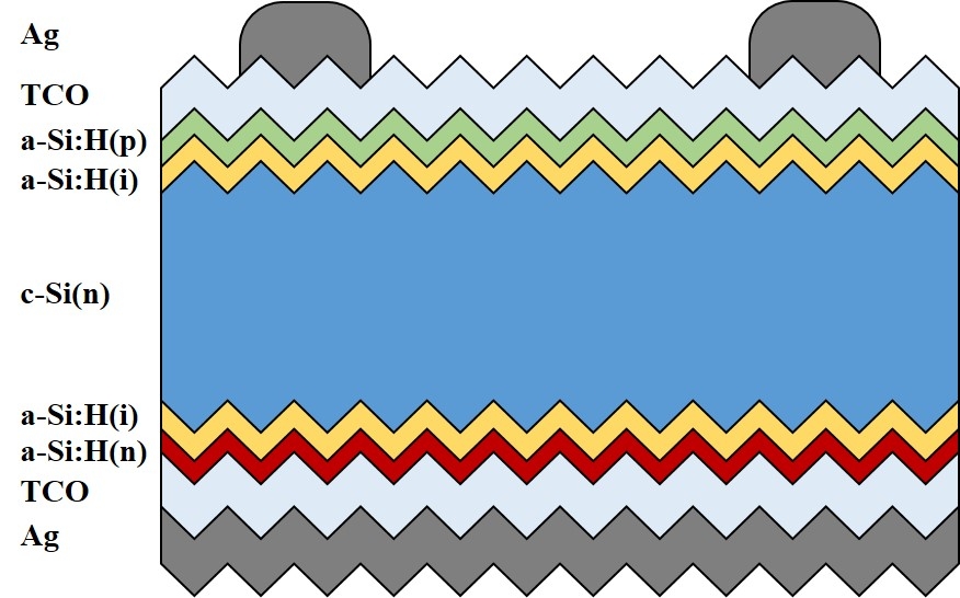
SHJ태양전지의 구조를 Fig. 1에 나타냈다. n형 단결정 wafer에 a-Si:H(p)와 a-Si:H(n) layer를 쌓아서 p-n접합을 형성하며 c-Si layer사이에는 a-Si:H(i) layer를 형성한다. Intrinsic layer는 c-Si 표면에 passivation을 해서 표면에서 생기는 recombination을 최소화하고, 개방전압과 열적안전성을 높이기 때문에 우수한 품질이 요구된다[13]. 마지막으로 a-Si:H(p) layer의 낮은 전도도를 보완하기위해 TCO와 금속전극을 형성한다. Fig. 1의 경우는 a-Si:H(p) layer가 전면에 있는 일반적인 HIT 구조이며, 후면에 형성하여 rear emitter로 캐리어의 손실을 낮추고 전기적 저항의 영향을 감소시키기는 구조가 연구되고 있다[14].
3. Indium Tin Oxide
태양전지에서 ITO의 역할은 전극과 반사방지막이다. 전극으로써의 주요 목적은 a-Si:H layer의 낮은 전도도와 금속접촉에서 생기는 손실을 줄이는 것이다. TCO중에서 ITO를 사용하는 이유는 얇은 두께에서도 전기적, 광학적 특성이 우수하기 때문이다.
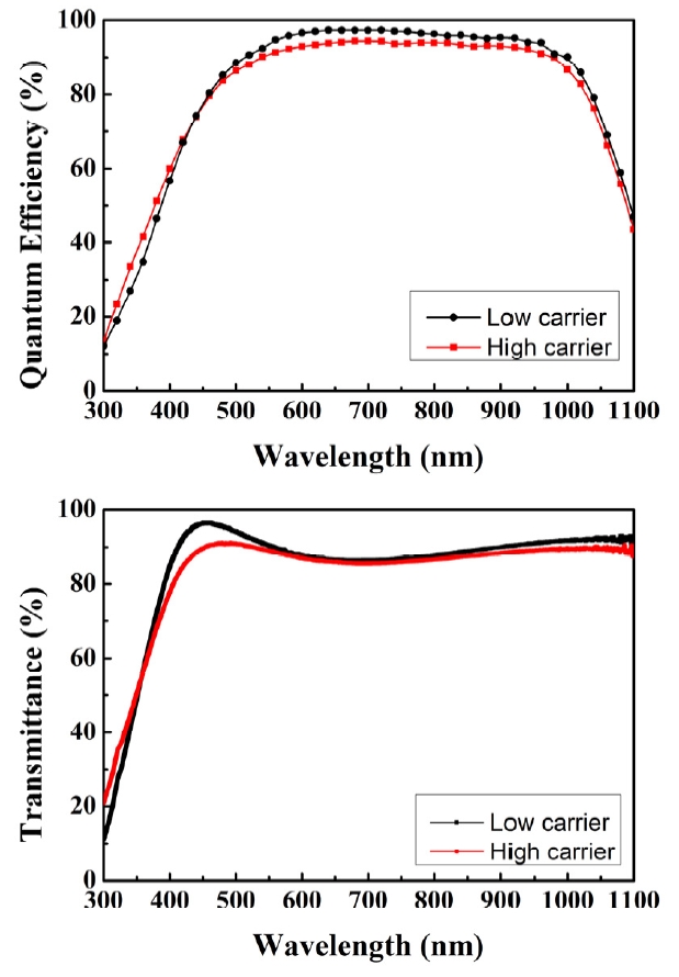
Fig. 2는 자유캐리어 농도에 따른 양자효율과 투과도 그래프이다. ITO는 가시광영역대에서 90%의 고 투과도를 갖는데[15], 투과되는 광량이 증가할수록 내부로 전달이 되는 캐리어생성량이 많아지기 때문에 current가 많아져서 JSC의 향상을 가져온다. 자유캐리어농도의 경우 캐리어의 수가 증가하게 되면 캐리어와 캐리어간의 충돌로 인해 FCA현상이 발생하여 빛이 투과하지 못하고 투과도가 감소한다[16]. Fig. 2에서 Low carrier가 고 투과도로 인하여 양자효율이 높지만, High carrier에서는 FCA현상으로 인해 투과도가 감소하여 양자효율도 감소한다. FCA현상을 최소화하기 위해 자유캐리어농도를 조절할 필요가 있다. 보통 In2O3와 SnO2의 조성은 대부분 각각 90wt%, 10wt%를 사용하는데, 자유캐리어농도를 감소시키기 위해 SnO2의 함량을 줄여 5wt%, 3wt%를 사용하기도 한다[17]. 하지만 자유캐리어 농도가 너무 감소하면 전도도가 낮아지기 때문에 FCA현상을 완화시키면서 전도성을 확보하는 trade-off가 있다.
이동도와 캐리어농도 또한 중요한 특성으로 ITO는 모상인 In2O3가 환원 분위기에서 분해 반응으로 인해 In203-x의 비 화학량론 조성을 형성해 n-type 전도성을 가지는데, 캐리어의 수가 제한적이기 때문에 투명전극으로 사용하기에 적은 값을 지니므로 불순물 원소를 도입하여 이를 보완한다[18]. 그 중 Sn4+ 이온을 첨가하는 ITO가 가장 우수한 방법으로 알려져 있어서 아직까지도 ITO를 주로 사용한다[19].
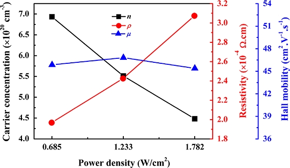
Fig. 3은 ITO 증착 파워 변화에 따른 전기적 특성들의 그래프이다. 증착 파워가 증가할수록 캐리어 농도가 감소하고 비저항은 상승한다. 하지만 이동도는 큰 차이를 보이지 않지만 이동도를 향상시키기 위해서 ITO증착 온도를 증가시키거나 어닐링을 통해 결정성을 개선시켜 새로운 결정면을 형성하면 이동도가 향상되어 전도도가 증가한다[21].
ITO를 증착이후 후속 열처리를 통해 특성을 개선시킬 수 있다. CO2 어닐링을 진행하게 되면 산소결함과 O-H결합이 감소하면서 결합이 향상되고 자유캐리어농도가 감소하게 되어 이동도가 증가한다[22]. O2 어닐링의 경우 산소원자가 반응하여 In203-x과 SnO2의 미 결합이 감소한다[23]. 결함이 감소하여 결합이 향상되고 결정성이 증가하는 것은 캐리어가 이동하는 것에 있어서 저항의 감소로 볼 수 있고, 이것은 면저항의 감소를 의미한다[24]. 투과도도 증가를 하는데, 내부의 형성된 결정들이 광 투과성을 향상시킨다. 고온에서 어닐링을 할수록 결정성이 많이 향상을 하지만[25], HIT 태양전지는 저온 공정이므로 어닐링으로 투과도를 향상시키기에는 한계가 있다.
다른 방법으로 결정성을 위해서 In2O3와 SnO2 모두 산소와의 결합이 존재하므로 ITO를 증착할 때 산소가스를 첨가하여 높이기도 한다[26].
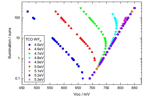
Fig. 4는 TCO의 일함수에 따른 VOC 변화를 illumination에 따라 나타낸 그래프이다. 1sun 에서의 VOC가 TCO의 일함수에 따라 증가한다. ITO의 일함수는 보통 4.1~4.7eV를 갖는다. ITO의 일함수가 4.7eV 이상을 확보해야 VOC의 감소를 막을 수 있다. 일함수는 ITO의 증착온도와 어닐링 조건에 따라 조절이 가능하다. ITO 증착 시 산소 분압이 증가하면 oxygen peak의 결정화도가 증가하여 indium의 binding energy가 증가하기 때문에 일함수가 증가하는데, ITO를 증착하면 a-Si:H(p) layer 사이에 barrier height를 형성하게 되고, 일함수를 높이면 barrier height를 낮출 수 있어서 hole injection을 원활하게 만든다[28]. 이를 통해 VOC와 FF 값이 향상된다.
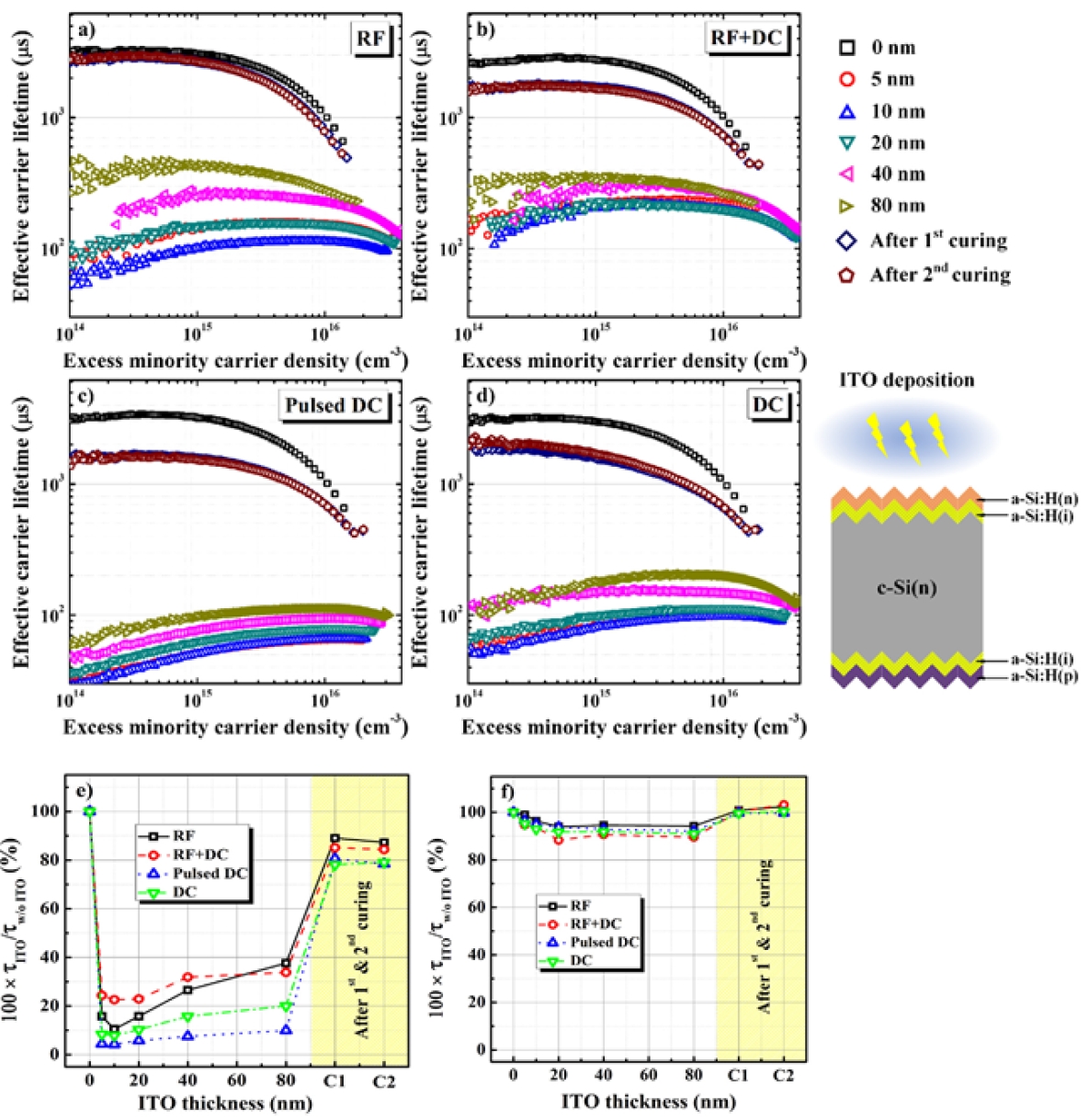
태양전지는 단일 막으로 존재하는 것이 아닌 Fig. 1에서처럼 a-Si:H layer가 있다. 높은 전력이나 고온에서 증착을 하게 되면 플라즈마가 layer에 영향을 가하여 박막 안으로 침투하거나 결정성을 생기게 만들어서 a-Si:H layer들의 특성을 감소시킬 수 있다. Fig. 5는 ITO 스퍼터 장비의 파워 종류에 따른 lifetime을 측정한 그래프이다. 파워는 RF와 DC를 주로 사용하는데, 플라즈마의 영향을 최소화하기 위해서 RF를 주로 사용한다. ITO의 증착 두께에 따라 lifetime이 감소하는데, RF 스퍼터를 사용할 경우 DC 스퍼터의 경우보다 감소량이 적다. 플라즈마 영향을 회복하기 위해 curing 공정을 통해 일부 회복이 가능하다[29]. 플라즈마에 의한 영향을 최소화하기 위해서 플라즈마의 강도를 줄이는 방법이 있다. 스퍼터링 증착 시 파워를 감소하고, 온도를 낮추어 직접적으로 플라즈마를 약하게 하는 방안이 있다. 플라즈마를 직접적인 노출로 인한 증착이 아닌 간접적으로 증착하는 방식과 플라즈마와 기판과의 거리를 증가시키는 방법처럼 같은 많은 연구가 이루어지고 있지만, 고품질의 박막을 유지하면서 플라즈마의 영향을 최소화하는 방법은 아직 요원하다.
4. Alternative TCO
ITO가 아닌 다른 TCO는 tin oxide가 아닌 zinc oixde를 도핑한 IZO 또는 IO:H가 있다. IO:H는 자유 캐리어 농도가 낮기 때문에 parasitic absorption이 적어 FCA의 영향이 낮아서 사용한다. IO:H와 IZO의 이동도가 ITO보다 30~50cm2/Vs 정도 높아서 JSC 값이 높다[31]. 하지만 IZO와 IO:H의 투과도는 ITO와 비교하면 300~400nm에서는 IZO와 IO:H가 상당히 높지만 450~800nm 구간에서는 ITO가 높다[32].
최근 새로운 물질의 TCO은 IWO가 있다. Panasonic에서 저밀도 IWO를 사용해 전극형성을 구현했다. IWO는 매우 높은 이동도와 투과율 특성이 있다[33]. 하지만 증착면의 균일도가 낮기 때문에 대량 및 대면적 생산이 불가능하다. 이를 위해서는 고밀도의 고효율 target이 요구되는데, target의 소결에 어려움이 있어 치밀도 형성의 어려움이 있다. 비슷한 이유로 ITiO의 사용을 하고 있다. IWO처럼 고 투과율과 고 이동도를 지닌다[34]. ITiO 역시 스퍼터링 target을 제작해야하는데, In2O3와 TiO2의 소결 거동에서 차이가 발생하여 양산의 어려움이 있다.
5. Conclusion
HIT 태양전지는 고효율이 가능한 태양전지로 많은 연구가 진행되었고, 초고효율을 위해서 ITO의 특성이 매우 중요해졌다. ITO는 고 투과도와 얇은 두께에서 우수한 전기적 특성을 갖는다. 하지만 스퍼터링으로 증착한 ITO의 플라즈마 데미지와 높은 자유캐리어농도를 공정조건의 변화, 후속 열처리를 통해 개선했다. ITO를 대신하기 위한 TCO가 연구되고 있지만 고 밀도의 target 생산이 어려움이 있다. 따라서 ITO의 특성을 향상시키는 방안이 모색될 전망이다.
Nomenclature
| JSC : | short circuit current density |
| VOC : | open circuit voltage |
Subscript
| SHJ : | silicon heterojunction |
| HIT : | heterojunction with intrinsic thin-layer |
| ITO : | indium tin oxide |
| BSF : | back surface field |
| TCO : | transparent conductive oxide |
| a-Si:H(i) : | intrinsic hydrogenated amorphous silicon |
| FF : | fill factor |
| FCA : | free carrier absorption |
| AR : | anti reflection |
| IO:H : | hydrogenated doped indium oxide |
| IWO : | indium tungsten oxide |
| ITiO : | indium titanium oxide |
| DC : | direct current |
| RF : | radio frequency |
Acknowledgments
이 논문은 2017년도 정부(산업통상자원부)의 재원으로 한국에너지기술평가원의 지원을 받아 수행된 연구임(2017301001294, 고효율 결정질 실리콘 태양전지용 전하선택접촉 기술 개발).
References
-
Ballif, C., Barraud, L., Descoeudres, A., Holman, Z.C., Morel, S., and Wolf, S.D., 2012, “A-Si:H/c-Si heterojunctions: a future mainstream technology for high-efficiency crystalline silicon solar cells?”, Proceedings of the 38th IEEE Photovoltaic Specialists Conference, 1705-1709.
[https://doi.org/10.1109/PVSC.2012.6317924]

-
Han, S.G., Shin, G.B., Park, S.Y., Ahn, S.H., Park, C.M., Kim, H.H., Cho, Y.H., and Yi, J.S., 2017, “A study on crystalline silicon solar cells using tunnel oxide layer for carrier selective contacts”, New. Renew. Energy, 13(3), 4-9.
[https://doi.org/10.7849/ksnre.2017.9.13.3.004]

- Wakisaka, K., Taguchi, M., Sawada, T., Tanaka, M., Matsuyama, T., Matsuoka, T., Tsuda, S., Nakano, S., Kishi, Y., and Kuwano, Y., 1991, “More than 16% solar cells with a new ‘HIT’ (doped a-Si/non doped a-Si/crystalline Si) structure”, Proceedings of the Conference Record of the Twenty-Second IEEE Photovoltaic Specialists Conference, 2, 887-892.
-
Mueller, T., Wong, J., and Aberle, A.G., 2012, “Heterojunction silicon wafer solar cells using amorphous silicon suboxides for interface passivation”, Energy Procedia, 15, 97-106.
[https://doi.org/10.1016/j.egypro.2012.02.012]

-
Green, M.A., Hishikawa, Y., Dunlop, E.D., Levi, D.H., Hohl-Ebinger, J., and Ho-Baillie, A.W.Y., 2018, “Solar cell efficiency tables (version 51)”, Progress in Photovoltaics Research and Applications, 26(1), 3-12.
[https://doi.org/10.1002/pip.2978]

-
Haschke, J., Dupre, O., Boccard, M., and Ballif, C., 2018, “Silicon heterojunction solar cells: recent technological development and practical aspects - from lab to industry”, Sol. Energy Mater. Sol. Cells, 187, 140-153.
[https://doi.org/10.1016/j.solmat.2018.07.018]

-
Park, H.S., Lee, Y.J., Park, J.J., Kim, Y.K., Lee, Y.S., Kim, S.H., Park, C.K., Lim, K.J., and Yi, J.S., 2018, “Front and back TCO research review of a‑.Si/c‑.Si heterojunction with intrinsic thin layer (HIT) solar cell”, Transactions on Electrical and Electronic Materials, 19(3), 165-172.
[https://doi.org/10.1007/s42341-018-0026-8]

-
Wolf, S.D., Descoeudres, A., Holman, Z.C., and Ballif, C., 2012, “High-efficiency Silicon Heterojunction Solar Cells: A Review”, Green, 2(1), 7-24.
[https://doi.org/10.1515/green-2011-0018]

-
Holman, Z.C., Descoeudres, A., Barraud, L., Fernandez, F.Z., Sief, J.P., Wolf, S.D., and Ballif, C., 2012, “Current losses at the front of silicon heterojunction solar cells”, IEEE journal of Photovoltaics, 2(1), 7-15.
[https://doi.org/10.1109/JPHOTOV.2011.2174967]

-
Tahar, R.B.H., Ban, T., Ohya, Y., and Takahashi, Y., 1998, “Tin doped indium oxide thin films: Electrical properties”, J. Appl. Phys., 83(5), 2631-2645.
[https://doi.org/10.1063/1.367025]

-
Centurioni, E., and Iencinella, D., 2003, “Role of front contact work function on amorphous silicon/crystalline silicon heterojunction solar cell performance”, IEEE Electron Device Lett., 24(3), 177-179.
[https://doi.org/10.1109/LED.2003.811405]

-
Kanevce, A., and Metzger, W.K., 2009, “The role of amorphous silicon and tunneling in heterojunction with intrinsic thin layer (HIT) solar cells”, J. Appl. Phys., 105(9), 095407, 1-7.
[https://doi.org/10.1063/1.3106642]

-
Aksari, M.B., and Eray, A., 2011, “Optimization of a-Si:H/c-Si Heterojunction Solar Cells By Numerical Simulation”, Energy Procedia, 10, 101-105.
[https://doi.org/10.1016/j.egypro.2011.10.160]

-
Diouf, D., Kleider, J.P., Desrues, T., and Ribeyron, P.J., 2009, “Study of interdigitated back contact silicon heterojunctions solar cells by two-dimensional numerical simulations”, Mater. Sci. Eng. : B, 159-160, 291-294.
[https://doi.org/10.1016/j.mseb.2008.09.002]

-
Heo, G.S., Gim, I.G., Park, J.W., Kim, K.Y., and Kim, T.W., 2009, “Effects of substrate temperature on properties of ITO-ZnO composition spread films fabricated by combinatorial RF magnetron sputtering”, J. Solid State Chem., 182(10), 2937-2940.
[https://doi.org/10.1016/j.jssc.2009.07.025]

-
Ellmer, K., and Mientus, R., 2008, “Carrier transport in polycrystalline transparent conductive oxides: A comparative study of zinc oxide and indium oxide”, Thin Solid Films, 516(14), 4620-4627.
[https://doi.org/10.1016/j.tsf.2007.05.084]

-
Murugesan, M., Arjunraj, D., Mayandi, J., Venkatachalapathy, V., and Pearce, J.M., 2018, “Properties of Al-doped zinc oxide and In-doped zinc oxide bilayer transparent conducting oxides for solar cell applications”, Mater. Lett., 222, 50-53.
[https://doi.org/10.1016/j.matlet.2018.03.097]

-
Hwang, J.H., Edwards, D.D., Kammler, D.R., and Mason, T.O., 2008, “Point defects and electrical properties of Sn-doped In-based transparent conducting oxides”, Solid State Ion., 129(1-4), 135-144.
[https://doi.org/10.1016/S0167-2738(99)00321-5]

-
Arockiadoss, T., Kovendhan, M., Joseph, D.P., Kumar, A.S., Choi, B.C., and Shim, K.S., 2018, “DC magnetron sputtered aligned ITO nano-rods with the influence of varying oxygen pressure”, Appl. Surf. Sci., 449, 39-47.
[https://doi.org/10.1016/j.apsusc.2017.12.129]

-
Le, A.H.T., Ahn, S.H., Han, S.M., Kim, J.M., Hussain, S.Q., Park, H.S., Park, C.M., Nguyen, C.P.T., Dao, V.I., and Yi, J.S., 2014, “Effective optimization of indium tin oxide films by a statistical approach for shallow emitter based crystalline silicon solar cell applications”, Sol. Energy Mater. Sol. Cells, 125, 176-183.
[https://doi.org/10.1016/j.solmat.2014.03.011]

-
Ali, A.H., Hassan, Z., and Shuhaimi, A., 2018, “Enhancement of optical transmittance and electrical resistivity of post-annealed ITO thin films RF sputtered on Si”, Appl. Surf. Sci., 443, 544-547.
[https://doi.org/10.1016/j.apsusc.2018.03.024]

-
Wang, F., Du, R., Ren, Q., Wei, C., Zhao, Y., and Zhang, X., 2017, “Improving crystallization and electron mobility of indium tin oxide by carbon dioxide and hydrogen dual-step plasma treatment”, Appl. Surf. Sci., 426, 856-863.
[https://doi.org/10.1016/j.apsusc.2017.07.182]

-
Kirner, S., Hartig, M., Mazzarella, L., Korte, L., Frijnts, T., Kurmes, H.S., Ring, S., Stannowki, B., Rech, B., and Schlatmann, R., 2015, “The influence of ITO dopant density on J-V characteristics of silicon heterojunction solar cells: experiments and simulations”, Energy Procedia, 77, 725-732.
[https://doi.org/10.1016/j.egypro.2015.07.103]

- Ahn, H.J., and Ha, K,R,, 2005, “Effect of substrate temperature and O2 introduction with ITO deposition by electron beam evaporation on polycyclic olefin polymer”, J. Ind. Eng. Chem., 16(6), 742-748.
-
Parida, B., Gil., Y.U., and Kim, H.S., 2019, “Highly transparent conducting indium tin oxide thin films prepared by radio frequency magnetron sputtering and thermal annealing”, J. Nanosci. Nanotechnol., 19(3), 1455-1462.
[https://doi.org/10.1166/jnn.2019.16242]

-
Sibin, K.P., Swain, N., Chowdhury, P., Dey, A., Sridhara, N., Shashikala, H.D., Sharma, A.K., and Barshilia, H.C., 2016, “Optical and electrical properties of ITO thin films sputtered on flexible FEP substrate as passive thermal control system for space applications”, Sol. Energy Mater. Sol. Cells, 145(3), 314-322.
[https://doi.org/10.1016/j.solmat.2015.10.035]

-
Ritzau, K.U., Bivour, M., Schroer, S., Steinkemper, H., Reinecke, P., Wagner, F., and Hermle, M., 2014, “TCO work function related transport losses at the a-Si:H/TCO-contact in SHJ solar cells”, Sol. Energy Mater. Sol. Cells, 131, 9-13.
[https://doi.org/10.1016/j.solmat.2014.06.026]

-
Oh, W.K., Hussain, S.Q., Lee, Y.J., Lee, Y.S., Ahn, S.H., and Yi, J.S., 2012, “Study on the ITO work function and hole injection barrier at the interface of ITO/a-Si:H(p) in amorphous/ crystalline silicon heterojunction solar cells”, Mater. Res. Bull., 47(10), 3032-3035.
[https://doi.org/10.1016/j.materresbull.2012.04.106]

-
Le, A.H.T., Dao, V.A., Pham, D.P., Kim, S.H., Dutta, S., Nguyen, C.P.T., Lee, Y.S., Kim, Y.K., and Yi, J.S., 2019, “Damage to passivation contact in silicon heterojunction solar cells by ITO sputtering under various plasma excitation modes”, Sol. Energy Mater. Sol. Cells, 192, 36-43.
[https://doi.org/10.1016/j.solmat.2018.12.001]

-
Yin, G., Steigert, A., Manley, P., Klenk, R., and Schmid, M., 2015, “Enhanced absorption in tandem solar cells by applying hydrogenated In2O3 as electrode”, Appl. Phys. Lett., 107(21), 211901, 1-5.
[https://doi.org/10.1063/1.4936328]

-
Masis, M.M., Nicolas, S.M.D., Holovsky, J., Wolf, S.D., and Ballif, C., 2015, “Low-temperature high-mobility amorphous IZO for silicon heterojunction solar cells”, IEEE Journal of Photovoltaics, 5(5), 1340-1347.
[https://doi.org/10.1109/JPHOTOV.2015.2450993]

-
Li, S., Shi, Z., Tang, Z., and Li, X., 2017, “Comparison of ITO, In2O3:Zn and In2O3:H transparent conductive oxides as front electrodes for silicon heterojunction solar cell applications”, Vacuum, 145, 262-267.
[https://doi.org/10.1016/j.vacuum.2017.09.011]

-
Kim, J.G., Na, S.I., and Kim, H.K., 2018, “Flexible and transparent IWO films prepared by plasma arc ion plating for flexible perovskite solar cells”, AIP Adv., 8(10), 105122, 1-8.
[https://doi.org/10.1063/1.5054347]

-
Ok, J.W., Oh, H.S., Kwak, D.J., Sung, Y.M., and Kim, S.H., 2015, “Effects of titanium doping concentration on the structural and electrical properties of sputtered indium oxide films”, J. Nanosci. Nanotechnol., 15(2), 1525-1528.
[https://doi.org/10.1166/jnn.2015.9337]


