고효율 결정질 실리콘 태양전지 적용을 위한 p타입 에미터 표면의 전계 효과를 이용한 실리콘 산화막 패시베이션
 ; Gyungbae Shim1) ; Sanguk Han1) ; Shihyun Ahn1) ; Cheolmin Park2) ; Younghyun Cho1) ; Hyunhoo Kim3) ; Junsin Yi1), *
© 2017 by the The Korean Society for New and Renewable Energy
This is an Open Access article distributed under the terms of the Creative Commons Attribution Non-Commercial License (http://creativecommons.org/licenses/by-nc/3.0) which permits unrestricted non-commercial use, distribution, and reproduction in any medium, provided the original work is properly cited.
Abstract
The surface passivation is one of the crucial steps to achieve high conversion efficiencies in c-Si solar cells. A thermally stable thin film with a negative charge (for p-type surface) passivation layer is required to develop a good front passivation suitable for n-type c-Si solar cells. Silicon suboxide (SiOX) layer using PECVD provides a good passivation layer which has low temperature process and charge control in thin-film layer. In this paper, a PECVD stack layer consisting of SiOX and SiNX was employed for front side passivation. The optimal refractive index of SiOX and SiNX were found by varying the silane (SiH4), ammonia (NH3) and nitrous oxide (N2O) gas ratio for decrease optical loss. -1.71 × 1011 cm-2 of negative charge (Qf) and 5×1010 cm-2 eV-1 of Dit (interface trap density) were obtained at 10 nm thick SiOX thin-film. With this optimized SiOx/SiNx stack layer on p+ surface wafer using PECVD, the effective lifetime of 280 ㎲ and implied VOC of 690 mV were achieved. It is expected that the efficiency of the n-type silicon solar cell can be improved by applying the optimized SiOx condition to the front passivation layer.
Keywords:
Silicon oxide, Negative charge, Plasma oxidation, Passivation키워드:
실리콘 산화막, 음전하, 플라즈마 산화법, 표면 패시베이션1. 서 론
PECVD(Plasma Enhanced Chemical Vapor Deposition)를 이용해 증착한 실리콘 질화막(SiNx:H)은 태양전지 제작에 있어 반사방지막(Anti-reflection coating layer)과 표면 passivation layer로 사용할 수 있다. 반사방지막과 passivation 뿐만 아니라 전기적 광학적으로 우수한 특성을 가지고 있는 SiNx는 실제 p-type 태양전지용 전면 passivation으로 널리 사용되었다[1-3]. 하지만 light induce degradation이 없고, metal 불순물에 의한 영향을 적게 받는 물성적으로 p-type 보다 유리한 n-type 웨이퍼의 전면 boron emitter상의 passivation으로는 positive charge를 가지는 SiNx는 적합하지 않다. n-type 태양전지의 경우 전면에서 minority 캐리어인 정공을 수집하는데 positive charge를 가지는 SiNx를 사용할 경우 쿨롬 척력(coulomb repulsive force)에 의해 정공의 수집이 어려워지고 재결합이 증가하여 Voc 및 Jsc가 감소하여 효율의 감소를 유발한다. 따라서 p-type emitter 표면의 passivation 으로는 positive charge를 띄는 SiNx가 아닌 negative charge를 가지는 다른 passivation 물질을 사용하여야 한다.
본 연구에서는 n-type 결정질 실리콘 태양전지 boron emitter의 passivation으로 적합한 negative charge를 가지는 SiOx layer를 증착하여 특성을 분석하여 최적화 연구를 수행하였다. 이를 위해 SiOx layer가 증착될 때 전구체(precursor)가 되는 SiH4와 N2O 가스비에 따른 굴절률과 계면에서의 defect인 Dit, layer의 charge 및 lifetime을 측정하여 n-type 결정질 실리콘 태양전지에 적용하기 위한 negative charge SiOx layer의 특성을 분석하였다.
2. 관련 이론
2.1 Passivation mechanism of SiOx
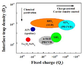
표면 passivation으로 bulk lifetime degradation을 극복하기 위해, PECVD에 의한 저온 SiOX 증착에 대한 많은 연구가 이루어져왔다[4-6]. 일반적으로 좋은 표면 passivation을 유도하는 두 가지 메커니즘이 있다[7]. (i) 계면에서 Dit의 감소 (ii) field effect passivation; 즉, passivation 층에 고정된 전하(Qf)를 줌으로써 하나의 캐리어 유형의 강력한 감소를 가져온다. 이러한 메카니즘 또는 이 둘의 조합은 낮은 표면 재결합 속도를 유도한다[8]. Fig. 1은 PECVD 혹은 sputter 등을 이용하여 증착할 수 있는 passivation material의 종류를 Dit와 Qf 별로 분류한 것이다. SiO2의 전형적인 값은 Dit = 1010cm-2eV-1 및 Qf = 1010cm-2이고 SiNX의 경우 Dit = 1011cm-2eV-1 및 Qf = 1011cm-2이다.
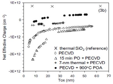
일반적으로 plasma를 이용한 산화막은 Qf 기준으로 neutral 영역에 위치하는데, 최근 PECVD를 이용하여 charge injection이나 두께 가변을 통해 Fig. 2와 같이 negative charge를 가지는 SiOX 막을 증착하는 실험이 진행되어졌다[9,10].
이러한 방법은 웨이퍼 표면상에 plasma damage로 인해 표면 defect이 증가하지만, furnace를 이용한 thermal oxidation 보다 저온에서 공정이 이루어지고, 공정시간이 짧을 뿐만 아니라 두께 조절이 용이하다는 장점을 가지고 있다. 또한 웨이퍼의 한 면만 선택적 증착이 가능하며 필요한 부분에만 산화막을 증착시키므로 process step을 줄일 수 있어, 공정시간의 단축과 비용절감의 효과를 볼 수 있다. 따라서 plasma damage를 최소한으로 하여, negative charge를 가지는 plasma oxidation은 보론 도핑 표면상의 passivation 효과의 향상 또한 기대할 수 있다.
3. 실험방법 및 결과
3.1 실험방법
모든 실험은 single PECVD를 이용한 증착을 기반으로 진행되었다. 이 장비의 고주파 발진기의 발진주파수는 13.56 MHz 이며 최대 출력은 600W 이다. 막이 증착되는 동안 반응 가스의 양을 조절하기 위해 MFC(Mass flow controller)를 사용하였다. Plasma를 이용한 산화막 증착은 O2, N2O 또는 CO2 가스들을 plasma를 이용하여 형성된 산화종들과 SiH4 가스의 실리콘 원자들의 결합으로 산화막이 증착된다. 본 실험에서는 RCA(SC1 / SC2) cleaning 후 HF에 dipping 하여 native oxide를 제거한 n-type 반도체 급과, p-type solar grade 웨이퍼에 SiH4와 N2O 가스를 이용하여 산화막을 증착하였다. 반도체 급 웨이퍼는 Table 1에서 볼 수 있듯이 SiH4 유량을 15 sccm, 기판 온도 400℃ 그리고 압력을 1 Torr로 고정한 조건에서 N2O 유량을 100 sccm에서 600 sccm으로 가변하여 증착이 진행되었다. 이 후 SiH4과 N2O 가스비를 고정시키고 두께와 RF-power를 가변 한 실험도 진행하였다. 증착한 막의 두께와 굴절률은 엘립소미터로 파장 600nm에서 측정 하였고, evaporator를 통해 알루미늄을 증착하여 상온에서 gate bias sweep이 10V~-10V인 고주파 C-V 측정을 진행하였다. C-V curve를 통해 막의 charge와 Dit를 확인하였다. 또한 solar grade 웨이퍼에는 SiOx의 상부층으로 SiNx를 capping하여 QSSPC (WCT-120)를 통해 lifetime과 implied Voc를 측정하여 최적화 실험을 진행하였다.
3.2 결과 및 고찰
Fig. 3a는 가스비 조건에 따른 막의 증착률과 굴절률의 변화 곡선이다. 막의 굴절률과 증착률 확인을 위한 엘립소미터 측정과 C-V curve, Dit 측정을 위한 증착은 모두 n-type 반도체급 웨이퍼 상에 진행되었다. 또한 반도체급 웨이퍼의 증착률을 바탕으로 solar grade 웨이퍼에 증착하였을 때 증착률 차이는 N2O 유량이 증가할수록 증착률이 감소하다가 500 sccm 이상의 유량에서 부터는 saturation 되었고, 굴절률은 유량의 증가에 따라 증가하다가 SiH4 15 sccm, N2O 500 sccm 조건에서 굴절률 1.46을 나타냈으며 그 이상의 유량에서는 감소하였다. 또한 Fig. 3b 에서는 C-V 측정을 통한 막의 Dit 계산 값을 나타내고 있으며 굴절률 1.46 조건이 5×1010cm-2eV-1 수준으로 가장 낮은 Dit 값을 가지는 것을 확인할 수 있었다.
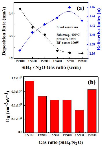
(a) Change of refractive index(n) and deposition rate of SiOX thin film with gas flow rate. (b) Comparison of Interface trap density of SiOX thin films with gas flow rate
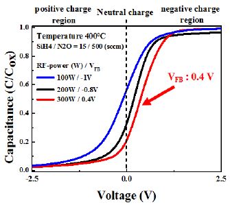
가장 낮은 Dit 값을 가지는 가스 비 SiH4 15 sccm, N2O 500 sccm 조건으로 RF-power를 100에서 300 W substrate temperature 100℃에서 300℃까지 가변 한 실험을 진행하였다. 증착된 막은 1.0MHz에서의 MIS(Metal-Insulator-Semiconductor) 구조에 대한 C-V 측정을 통해 VFB 값으로 charge의 변화와 Dit 값을 계산하여 기존의 SiNx 막과 비교하였다. Fig. 4의 C-V curve를 보면, 100W 와 200W 에서는 (-)의 VFB 값을 나타내지만 300W 에서는 0.4V로 neutral에 근사하지만 파워가 증가함에 따라 negative charge region으로 VFB가 shift 되는 경향을 확인하였다.
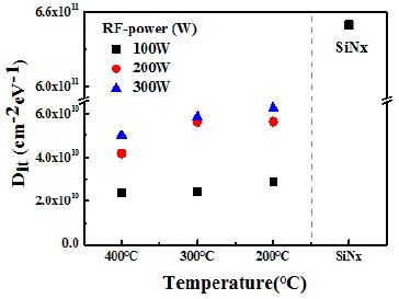
서로 다른 substrate temperature 에서 모두 RF-power가 증가할수록 plasma damage에 의해 Dit 값이 증가하는 경향을 보인다. Substrate temperature가 높아질수록 Dit값이 낮아지는 것을 확인할 수 있으며 400℃, 300W의 조건에서 5 × 1010cm-2eV-1 정도의 값으로 5 × 1011cm-2eV-1 의 값을 가지는 기존의 SiNX와 비교하였을 때, 훨씬 낮은 수치의 값을 가지는 것을 Fig. 5를 통해 확인하였다.
Comparison of Dit of SiOX according to RF-power and substrate temperature versus Dit of SiNX in optimized condition
Fig. 6a에서는 SiH4 15 sccm, N2O 500 sccm의 가스비와 RF-power 300W의 조건으로 증착한 10nm~30nm의 두께를 가진 실리콘 산화막에 대한 C-V 곡선을 나타내고 있으며, 두께가 10nm 인 SiOX 층의 경우, SiOX 막에서 양의 고정 된 트랩으로 인해 VFB가 음의 영역으로 이동한다. 이러한 VFB는 절연체 박막 내의 고정 전하와 포획되어 있는 전하의 양에 비례해서 커지기 때문에 이를 통해 박막의 두께에 따른 charge와 passivation 효과 차이를 분석할 수 있다[11]. 10nm 두께의 산화막에서 측정된 1.24V의 VFB는 MIS 구조에 대한 C-V 측정으로부터 얻어졌으며, VFB를 통해 산화막에 대한 Qf의 값은 식 (1)을[12] 통해 계산 될 수 있다.
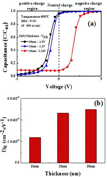
(a) Change of C-V curve according to thickness of SiOx thin film and (b) Comparison of interface trap density of optimized SiOx thin films with various thickness
| (1) |
Ci는 절연체 커패시턴스이고, A는 다이오드의 면적이며, Φms는 금속과 실리콘 사이의 일함수 차이다(이 연구에서 금속 전극으로 사용 된 알루미늄은 Φms ≒ 0.87 eV). 10nm 두께에서 측정한 1.24V의 VFB를 수식 (2)을 통하여 Qf : -1.71 × 1011cm-2 의 negative charge를 가지는 것을 확인하였다. 또한 각 산화막의 두께가 얇아질수록 5 × 1010cm-2eV-1 에서 2 × 1010cm-2eV-1 수준까지 Dit가 감소되는 경향을 나타냈다.
| (2) |
| (3) |
식 (2)는 τeffective(effective lifetime)와 SRV(surface recombination velocity)의 상관관계를 나타내는 식으로 반비례 관계를 가지고 있다. 또한 식 (3)은 SRV와 Dit가 비례하는 것을 확인할 수 있다. 따라서 Dit와 lifetime은 반비례 관계이며 즉 Dit의 감소는 lifetime의 증가라는 결론을 확인할 수 있었고, 가장 낮은 Dit 값을 가지는 최적조건을 이용하여 passivation layer를 증착하였다.
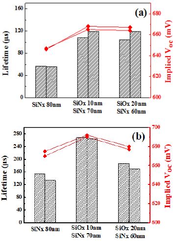
기존의 결정질 실리콘 태양전지에도 SiOX layer를 passivation layer로 사용하여 태양전지의 성능을 향상시키는 방법이 연구되었다. SiOX 와 SiNX layer를 적층구조로 증착한 후 750℃에서 30초 동안 소성 공정을 하였을 때 SiOX layer가 있는 샘플에서 보다 좋은 passivation 결과를 보였다. 이 passivation 효과는 소성 공정을 거친 후에 향상 되는 것을 확인하였다[13]. 위의 가변 실험들을 통해 최적화된 증착 조건 의 passivation 특성을 평가하기 위해 solar grade p-type 웨이퍼에 양면으로 SiNX(80nm)와 SiOX (10nm / 20nm) 위에 SiNX(70nm / 60nm)를 capping layer로 증착하여 QSSPC를 통해 lifetime 과 implied VOC를 측정 비교하였다. Fig. 7의 모든 조건의 샘플이 소성 공정 후에 향상 되지만, 결과가 SiNx는 150㎲, 20nm와 10nm SiOX 조건이 각각 200㎲, 270㎲ 의 lifetime 결과를 확인하였다. Implied Voc 또한 소성 후 SiNx는 670 mV였지만, 10nm 조건에서 최고 690mV 까지 향상되는 것을 확인하였다. 이 실험들을 통해 SiH4 15sccm N2O 500 sccm 가스비와 기판온도 400℃, RF-power 300W 그리고 압력 1 Torr에서 최적의 조건을 확립하였다.
4. 결 론
본 연구에서는 PECVD를 이용해 thermal oxidation의 고온공정 및 긴 공정시간 등의 단점들을 보완할 수 있는 plasma oxidation에 대한 최적화 연구를 진행하였다. 최적화 조건을 통해 10nm 두께로 증착시킨 실리콘 산화막들은 최저 –1.71 × 10¹¹ 의 negative charge를 가지는 박막을 형성하였다. 또한 5 × 1010cm-2eV-1 수준의 Dit 값을 가지고 있으면서, SiOX passivation을 이용한 재결합 감소 및 전계 효과를 통한 캐리어의 수집 향상으로 lifetime과 implied VOC값의 증가를 확인하였다. 본 연구결과를 통해 최적화 된 negatived charge SiOX를 전면 passivation layer에 적용 한다면 선택적 산화막 증착으로 공정 시간과 비용 감소를 통해 고효율의 태양전지 제작이 가능할 것으로 판단된다.
Acknowledgments
본 연구는 산업통상자원부(MOTIE)와 한국에너지기술평가원(KETEP)의 지원을 받아 수행한 연구 과제입니다(No.20173010012940).
References
- Wolf, R., Wandel, K., Gruska, B., (2001), “Low-temperature ICPECVD of silicon nitride in SiH4–NH3–Ar discharges analyzed by spectroscopic ellipsometry and etch behavior in KOH and BHF”, Surface and Coatings Technology, 142, p786-791.
-
Jana, T., Mukhopadhyay, S., Ray, S., (2002), “Low temperature silicon oxide and nitride for surface passivation of silicon solar cells”, Solar energy materials and solar cells, 71(2), p197-211.
[https://doi.org/10.1016/s0927-0248(01)00058-7]

-
Duerinckx, F., Szlufcik, J., (2002), “Defect passivation of industrial multicrystalline solar cells based on PECVD silicon nitride”, Solar energy materials and solar cells, 72(1), p231-246.
[https://doi.org/10.1016/s0927-0248(01)00170-2]

- Hofmann, M., Janz, S., Schmidt, C., Kambor, S., Suwito, D., Kohn, N., Glunz, S. W., (2009), “Recent developments in rear-surface passivation”, at Fraunhofer ISE. Solar energy Materials and Solar cells, 93(6), p1074-1078.
-
Zhou, H. P., Wei, D. Y., Xu, S., Xiao, S. Q., Xu, L. X., Huang, S. Y., Xu, M., (2012), “Si surface passivation by SiOX: H films deposited by a low-frequency ICP for solar cell applications”, Journal of Physics D: Applied Physics, 45(39), p395401.
[https://doi.org/10.1088/0022-3727/45/39/395401]

-
Hoex, B., Peeters, F. J. J., Creatore, M., Blauw, M. A., Kessels, W. M. M., van de Sanden, M. C. M., (2006), “High-rate plasma-deposited SiO2 films for surface passivation of crystalline silicon”, Journal of Vacuum Science & Technology A: Vacuum, Sufaces, and Films, 24(5), p1823-1830.
[https://doi.org/10.1116/1.2232580]

- Aberle, A. G., (1999), “Crystalline silicon solar cells: advanced surface passivation and an crystalline silicon”, Journal of Vacuum Science & Technology A: Vacuum, Surfaces and Films, 24(5), p1823-1830, alysis”, Centre for Photovoltaic Engineering. University of New South Wales.
-
Glunz, S. W., (2007), “High-efficiency crystalline silicon solar cells”, Advances in OptoElectronics.
[https://doi.org/10.1155/2007/97370]

-
Boogaard, A., Kovalgin, A. Y., Wolters, R. A. M., (2009), “Net negative charge in low-temperature SiO2 gate dielectric layers”, Microelectronic engineering, 86(7), p1707-1710.
[https://doi.org/10.1016/j.mee.2009.03.124]

-
Cho, E., Ok, Y. W., Hwang, J., Upadhyaya, A. D., Tate, J. K., Zimbardi, F., Rohatgi, A., (2016), “Field-effect passivation by charge injection into SiNX using a novel low-cost plasma charging method”, Photovoltaic Specialists Conference (PVSC), 2016 IEEE 43rd, p2874-2877.
[https://doi.org/10.1109/pvsc.2016.7750180]

- Lee, D. Y., Lee, H. H., Ahn, J. Y., Park, H. J., Kim, J. H., Kwon, H. J., Jeong, J. W., (2011), “A new back surface passivation stack for thin crystalline silicon solar cells with screen-printed back contacts”, Solar Energy Materials and Solar Cells, 95(1), p26-29.
-
Lelièvre, J. F., Fourmond, E., Kaminski, A., Palais, O., Ballutaud, D., Lemiti, M., (2009), “Study of the composition of hydrogenated silicon nitride SiNx: H for efficient surface and bulk passivation of silicon”, Solar Energy Materials and Solar Cells, 93(8), p1281-1289.
[https://doi.org/10.1016/j.solmat.2009.01.023]

-
Heng, J. B., Fu, J., Kong, B., Chae, Y., Wang, W., Xie, Z., Erben, C., (2015), “> 23% high-efficiency tunnel oxide junction bifacial solar cell with electroplated Cu gridlines”, IEEE Journal of Photovoltaics, 5(1), p82-86.
[https://doi.org/10.1109/jphotov.2014.2360565]

